
Concept explainers
Videos
Find the unknown values in the circuit if the total current is 1.2 A and the resistors have the following values:
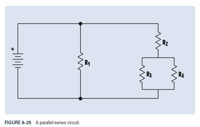
FIGURE 8-25 A parallel-series circuit.
Want to see the full answer?
Check out a sample textbook solution
Chapter 8 Solutions
DELMAR'S STANDARD TEXT OF ELECTRICITY


- I want to find the current by using mesh analysis pleasearrow_forwardR₁ W +10 V R3 +9 V C₂ R₁ CA C₁ 470 pF HH 1000 pF HH 1 με C4 1 μF 1 uF C₁ R₂ R4 100 pF Find Open-loop Jain L₁ 5 mH (a) Av=S,B={" H R₁₂ ✓ ww (b) R₁ L₁ 000 1.5 mH R₂ H 1 uF 12 10 mHarrow_forwardA) Calculate the efficiency of the test transformer at the resistive loads (X-25%, 50%, 75%, 100%, 125% full load). B) From part (A) draw the plot (efficiency Vs power output) of the transformer. C) Discuss the plot of part (B).arrow_forward
- a- Determine fH; and Ho b- Find fg and fr. c- Sketch the frequency response for the high-frequency region using a Bode plot and determine the cutoff frequency. Ans: 277.89 KHz; 2.73 MHz; 895.56 KHz; 107.47 MHz. 14V Cw=5pF Cwo-8pF Coc-12 pF 5.6kQ Ch. 40. pF C-8pF 68kQ 0.47µF Vo 0.82 kQ V₁ B=120 0.47µF www 3.3kQ 10kQ 1.2kQ =20µF Narrow_forwardUsing D flip-flops, design a synchronous counter. The counter counts in the sequence 1,3,5,7, 1,7,5,3,1,3,5,7,.... when its enable input x is equal to 1; otherwise, the counter. This counter is for individual settings only need the state diagram and need the state table to use 16 states from So to S15.arrow_forward: A sequential network has one input (X) and two outputs (Z1 and Z2). An output Z1 Z2 = 10 occurs every time the input sequence 1011 is completed. An output Z1 Z2 = 01 occurs every time the input sequence 0101 is completed. Otherwise Z1 Z2 = 0 Find Moore state diagram with minimum number of states: a) When overlap is allowed. b) When overlap is not allowed. I need a step by step printable solution that uses sequences on the same drawing.arrow_forward
- 1. Consider a negative unity-feedback control system whose plant transfer function is type- 1. Suppose you want to build a lead compensator so that -3 ± 5j are dominant poles. You observed that the angle deficiency at the desired dominant pole is 50°. Compute a 's+b' and b of the lead compensator (s+ 2) so that the error constant Ky is maximized. In other words, design the lead compensator in a way so that the steady-state error for ramp input is minimumarrow_forwardEXAMPLE 8.12 The E-MOSFET of Fig. 8.40 was analyzed in Example 7.10, with the result that k = 0.24 × 10³ A/V², VGS = 6.4 V, and ID = 2.75 mA. a. Determine gm- b. Find rd. c. Calculate Z; with and without rd. Compare results. d. Find Zo with and without ra. Compare results. e. Find A, with and without rd. Compare results. 카 1 uF Z RE 912 V Rp • 2 ΚΩ 10 ΜΩ HE 1 μF ID (on) = 6 mA VGS (on) = 8 V VGS (Th) = 3 V 80s = 20 μs Za o Voarrow_forwardNO AI PLEASEarrow_forward
- NO AI PLEASEarrow_forwardI need handwritten solution to this, electrical engineering expert tutor s only,this is an assignment,I need 100% accuracyarrow_forward5. Determine the CT convolutions for the signals below. Sketch the signal that flips and on same plot the one that is not flipped. Do this for each overlap case. Clearly indicate all overlap cases and the integral limits. Finally, using the left squiggly bracket notation, show the output for each case versus time. (c) 4 x(t) 2 1 2(t) 4 x(t) 4 0123 et 20 x(t) (4) 4 (a) +(1) 24 T 0123 (b) T (f) 1 2-2 0123 (c) (f) 0123 (d) (1) A t 1(8) 4,121 -101 3 (e)arrow_forward
 Introductory Circuit Analysis (13th Edition)Electrical EngineeringISBN:9780133923605Author:Robert L. BoylestadPublisher:PEARSON
 Delmar's Standard Textbook Of ElectricityElectrical EngineeringISBN:9781337900348Author:Stephen L. HermanPublisher:Cengage Learning
 Programmable Logic ControllersElectrical EngineeringISBN:9780073373843Author:Frank D. PetruzellaPublisher:McGraw-Hill Education
 Fundamentals of Electric CircuitsElectrical EngineeringISBN:9780078028229Author:Charles K Alexander, Matthew SadikuPublisher:McGraw-Hill Education
 Electric Circuits. (11th Edition)Electrical EngineeringISBN:9780134746968Author:James W. Nilsson, Susan RiedelPublisher:PEARSON
 Engineering ElectromagneticsElectrical EngineeringISBN:9780078028151Author:Hayt, William H. (william Hart), Jr, BUCK, John A.Publisher:Mcgraw-hill Education,