
Find the vertical stress increase at 4 m below A, B, and C.
Answer to Problem 8.27CTP
The increase in the vertical stress
The increase in the vertical stress
The increase in the vertical stress
Explanation of Solution
Given information:
The depth of the point from the ground level,
The intensity of the uniform pressure,
Calculation:
Vertical stress increase at point A:
Show the free-body diagram of the L-shaped raft as in Figure 1.
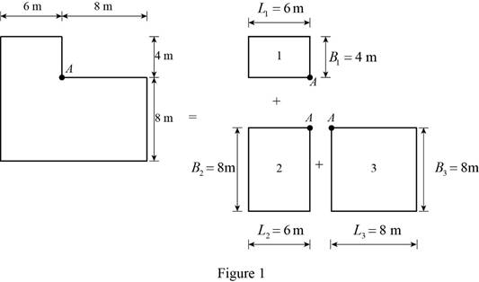
Rectangle 1:
Find the value of
Substitute 4 m for
Find the value of
Substitute 6 m for
Refer Figure 8.16 “Variation of
For
The value of variation
Find the increase in vertical stress
Substitute
Rectangle 2:
Find the value of
Substitute 8 m for
Find the value of
Substitute 6 m for
Refer Figure 8.16 “Variation of
For
The value of variation
Find the increase in vertical stress
Substitute
Rectangle 3:
Find the value of
Substitute 8 m for
Find the value of
Substitute 8 m for
Refer Figure 8.16 “Variation of
For
The value of variation
Find the increase in vertical stress
Substitute
Find the increase in vertical stress
Substitute
Therefore, the increase in the vertical stress
The vertical stress increase at point B:
Show the free-body diagram of the L-shaped raft as in Figure 2.
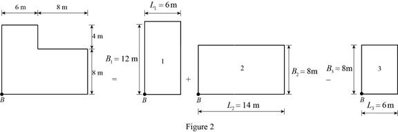
Rectangle 1:
Find the value of
Substitute 12 m for
Find the value of
Substitute 6 m for
Refer Figure 8.16 “Variation of
For
The value of variation
Find the increase in vertical stress
Substitute
Rectangle 2:
Find the value of
Substitute 8 m for
Find the value of
Substitute 14 m for
Refer Figure 8.16 “Variation of
For
The value of variation
Find the increase in vertical stress
Substitute
Rectangle 3:
Find the value of
Substitute 8 m for
Find the value of
Substitute 6 m for
Refer Figure 8.16 “Variation of
For
The value of variation
Find the increase in vertical stress
Substitute
Find the increase in vertical stress
Substitute
Therefore, the increase in the vertical stress
The vertical stress increase at point C:
Show the free-body diagram of the L-shaped raft as in Figure 3.
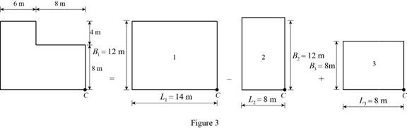
Rectangle 1:
Find the value of
Substitute 12 m for
Find the value of
Substitute 14 m for
Refer Figure 8.16 “Variation of
For
The value of variation
Find the increase in vertical stress
Substitute
Rectangle 2:
Find the value of
Substitute 12 m for
Find the value of
Substitute 8 m for
Refer Figure 8.16 “Variation of
For
The value of variation
Find the increase in vertical stress
Substitute
Rectangle 3:
Find the value of
Substitute 8 m for
Find the value of
Substitute 8 m for
Refer Figure 8.16 “Variation of
For
The value of variation
Find the increase in vertical stress
Substitute
Find the increase in vertical stress
Substitute
Therefore, the increase in the vertical stress
Want to see more full solutions like this?
Chapter 8 Solutions
EBK FUNDAMENTALS OF GEOTECHNICAL ENGINE

- I have the answers for part a just need help with b mostly thanksarrow_forwardPlease explain step by step and show formulasarrow_forward5. (20 Points) Consider a channel width change in the same 7-foot wide rectangular in Problem 4. The horizontal channel narrows as depicted below. The flow rate is 90 cfs, and the energy loss (headloss) through the transition is 0.05 feet. The water depth at the entrance to the transition is initially 4'. 1 b₁ TOTAL ENERGY LINE V² 129 У1 I b₂ TOP VIEW 2 PROFILE VIEW h₁ = 0.05 EGL Y₂ = ? a) b) c) 2 Determine the width, b₂ that will cause a choke at location 2. Determine the water depth at the downstream end of the channel transition (y₂) section if b₂ = 5 feet. Calculate the change in water level after the transition. Plot the specific energy diagram showing all key points. Provide printout in homework. d) What will occur if b₂ = = 1.5 ft.?arrow_forward
- 4. (20 Points) A transition section has been proposed to raise the bed level a height Dz in a 7-foot wide rectangular channel. The design flow rate in the channel is 90 cfs, and the energy loss (headloss) through the transition is 0.05 feet. The water depth at the entrance to the transition section is initially 4 feet. b₁ = b = b2 1 TOTAL ENERGY LINE V² 129 Ут TOP VIEW 2 hloss = 0.05 " EGL Y₂ = ? PROFILE VIEW a) Determine the minimum bed level rise, Dz, which will choke the flow. b) If the step height, Dz = 1 ft, determine the water depth (y2) at the downstream end of the channel transition section. Calculate the amount the water level drops or rises over the step. c) Plot the specific energy diagram showing all key points. Provide printout in Bework. d) What will occur if Dz = 3.0 ft.?. Crest Front Viewarrow_forward1. (20 Points) Determine the critical depth in the trapezoidal drainage ditch shown below. The slope of the ditch is 0.0016, the side slopes are 1V:2.5H, the bottom width is b = 14', and the design discharge is 500 cfs. At this discharge the depth is y = 4.25'. Also, determine the flow regime and calculate the Froude number. Ye= ? Z barrow_forward3. (20 Points) A broad crested weir, 10 feet high, will be constructed in a rectangular channel B feet wide. The weir crest extends a length of B = 120 feet between the banks with 2 - 4 foot wide, round nosed piers in the channel. The width of the weir crest is 8 feet. If H = 6', determine the design discharge for the weir.arrow_forward
- Parking Needs vs. Alternative Transportation Methods for presentation slides include images and graphsarrow_forwardPlease explain step by step and show formulararrow_forwardBeam ABD is supported and loaded as shown. The cross-section of the beam is also shown. The modulus of elasticity of the beam is 200 GPa. 6.0 kN/m Cross-section: 330 mm 4.5 kN 8.0 kNm 40 mm 2.5 m 1.5 m 20 mm Set up the discontinuity moment function in terms of x. List all the appropriate boundary conditions. Determine the slope function in terms of x. Determine the deflection function in terms of x. Determine the support reactions. Determine the maximum deflection. 290 mmarrow_forward
- Draw the Shear Force Diagram and Bending Moment Diagram for the beam shown in Fig.1. The beam is subjected to an UDL of w=65m. L=4.5m L1= 1.8m. Assume the support at C is pinned, and A and B are roller supports. E = 200GPa, I = 250x106 mm4.arrow_forwardCalculate the BMs (bending moments) at all the joints of the beam shown in Fig.1 using the Slope Deflection method. The beam is subjected to an UDL of w=65m. L=4.5m L1= 1.8m. Assume the support at C is pinned, and A and B are roller supports. E = 200GPa, I = 250x106 mm4.arrow_forwardText Book Problem 7.82 (page 261) Consider the total head-loss in the system forthis flow is 18.56 ft (head-losses in first and second pipe are 13.83 ft and 4.73 ftrespectively). Please show numerical values for EGL/HGL at the beginning/end/intermediatechange point. (Point distribution: elevation determination 5 points, EGL, HGL lines 4points).(I think we are just using the values provided for head losses to solve this problem)arrow_forward
 Fundamentals of Geotechnical Engineering (MindTap...Civil EngineeringISBN:9781305635180Author:Braja M. Das, Nagaratnam SivakuganPublisher:Cengage Learning
 Principles of Foundation Engineering (MindTap Cou...Civil EngineeringISBN:9781337705028Author:Braja M. Das, Nagaratnam SivakuganPublisher:Cengage Learning
 Principles of Geotechnical Engineering (MindTap C...Civil EngineeringISBN:9781305970939Author:Braja M. Das, Khaled SobhanPublisher:Cengage Learning
 Principles of Foundation Engineering (MindTap Cou...Civil EngineeringISBN:9781305081550Author:Braja M. DasPublisher:Cengage Learning