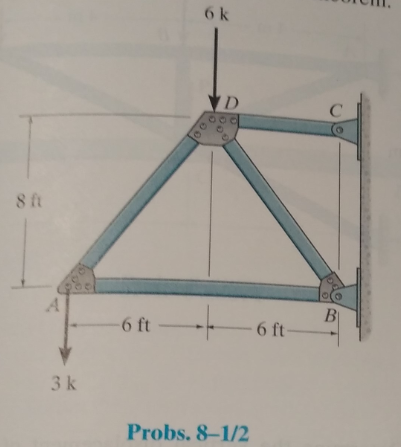
Determine the vertical displacement of joint A. Assume the members are pin connected at their end points. Take A = 3 in2 and E = 29(103) ksi for each member. Use the method of virtual work.
Vertical displacement of Joint A
Answer to Problem 8.1P
Explanation of Solution
Given information:
The members are pin connected at end points.
A = 3 in2
E = 29(103) ksi
Virtual Work Method
Virtual external work done = Sum of the internal work done
Calculation:
The virtual and real member forces are calculated by method of joints.
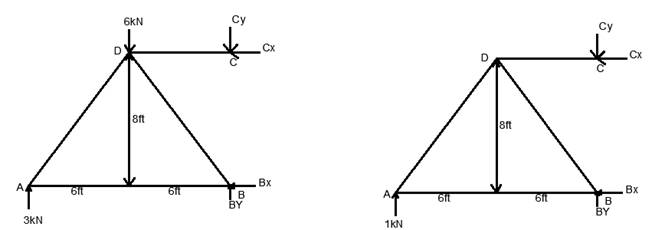
Member forces when original load is applied:
Taking moment about B, we get,
Joint A:
Joint B:
Joint D:
Member forces when virtual load is applied:
Taking moment about B, we get,
Joint A:
Joint B:
Joint D:
Conclusion:
Want to see more full solutions like this?
Chapter 8 Solutions
Structural Analysis, Student Value Edition
Additional Engineering Textbook Solutions
Java: An Introduction to Problem Solving and Programming (8th Edition)
Web Development and Design Foundations with HTML5 (8th Edition)
Modern Database Management
Starting Out with Java: From Control Structures through Objects (7th Edition) (What's New in Computer Science)
Database Concepts (8th Edition)
Starting Out with Programming Logic and Design (5th Edition) (What's New in Computer Science)

- Need help!! in this martin luther king jr. day is a non working dayarrow_forwardThe plan and 3D elevation of an earth retaining structure used for support excavation is shown in Figs. 3 and 4 respectively. The retaining structure is made of wood planks supported in the horizontal direction on vertical steel piles (HP sections). The HP piles shape of an H and are typically used for piles. The section properties of these sections (A, I, S, etc…) are given in Part 1 of the AISC steel manual. The spacing of the supporting HP piles is 20ft. The height of the piles is 15 from top of the pile to top of the footing. The height of the water table from the top of the footing is 9 ft as shown in the elevation in Fig. 4. The pile height and soil properties and the earth pressure distribution behind the retaining structure are shown in Fig. 5. Figs. 6 shows the equations for earth pressure. q is a live load surcharge that accounts for traffic on top of the embankment; q is typically assumed to be 250 psf (per the bridge code (AASHTO)). Use Fy = 50 ksi 1. Determine…arrow_forwardfind SFD and BMD? where at node K the load is 25 kiparrow_forward
- find SFD and BMDarrow_forwardNote: Please provide a clear, step-by-step, simplified handwritten working out (no explanations!), ensuring it is completed without any AI involvement. I require an expert-level answer and will assess and rate your work based on its quality and accuracy, refer to the provided image for additional clarity. Make sure to double-check everything for correctness before submitting. Thanks, appreciate your time and effort!.arrow_forwardNeed help!! Add martin luther king jr day as a holiday so it won't be a work dayarrow_forward
- ضهقعفكضكشتبتلتيزذظظؤوروىووؤءظكصحبت٢٨٩٤٨٤ع٣خ٩@@@#&#)@)arrow_forwardA steel rod 100 ft long holds a 200 lb weight as shown. If the diameter of the circular rod is ¼ inch, find the maximum normal stress in the road, taking into account the weight of the rod itself. Use: density of steel = ϒ = 490 lb/ft3 .arrow_forwardضهقعفكضكشتبتلتيزذظظؤوروىووؤءظكصحبت٢٨٩٤٨٤ع٣خ٩@@@#&#)@)arrow_forward
- ضهقعفكضكشتبتلتيزذظظؤوروىووؤءظكصحبت٢٨٩٤٨٤ع٣خ٩@@@#&#)@)arrow_forwardA square flexible foundation of width B applies a uniform pressure go to the underlying ground. (a) Determine the vertical stress increase at a depth of 0.5B below the center using Aσ beneath the corner of a uniform rectangular load given by Aσ Variation of Influence Value I m n 0.5 0.6 0.8 1.0 0.2 0.4 0.2 0.01790 0.03280 0.03866 0.04348 0.05042 0.05471 0.4 0.03280 0.06024 0.07111 0.08009 0.09314 0.10129 0.5 0.03866 0.07111 0.08403 0.09473 0.11035 0.12018 0.6 0.04348 0.08009 0.09473 0.10688 0.12474 0.13605 0.8 0.05042 0.09314 0.11035 0.12474 0.14607 0.15978 1.0 0.05471 0.10129 0.12018 0.13605 0.15978 0.17522 (Enter your answer to three significant figures.) Ασ/90 = Activity Frame (b) Determine the vertical stress increase at a depth of 0.5B below the center using the 2 : 1 method equation below. 90 x B x L Aσ = (B+ z) (L+ z) (Enter your answer to three significant figures.) Δσ/90 = (c) Determine the vertical stress increase at a depth of 0.5B below the center using stress isobars in…arrow_forwardNeed help!!!arrow_forward
 Principles of Foundation Engineering (MindTap Cou...Civil EngineeringISBN:9781305081550Author:Braja M. DasPublisher:Cengage Learning
 Steel Design (Activate Learning with these NEW ti...Civil EngineeringISBN:9781337094740Author:Segui, William T.Publisher:Cengage Learning
 Principles of Foundation Engineering (MindTap Cou...Civil EngineeringISBN:9781337705028Author:Braja M. Das, Nagaratnam SivakuganPublisher:Cengage Learning
 Materials Science And Engineering PropertiesCivil EngineeringISBN:9781111988609Author:Charles GilmorePublisher:Cengage Learning
 Engineering Fundamentals: An Introduction to Engi...Civil EngineeringISBN:9781305084766Author:Saeed MoaveniPublisher:Cengage Learning