
Videos
(a)
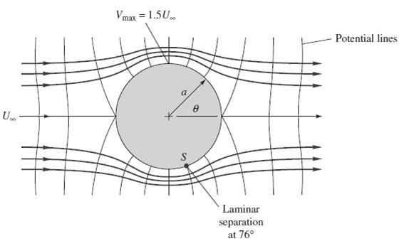
The point on the front surface where the fluid acceleration is maximum.
Answer to Problem 8.103P
The required value of the placement of the point is
Explanation of Solution
Given Information:

Formula used:
Calculation:
We know the formula for the maximum acceleration, i.e.:
Put the values in the above equation;
(b)
The value of maximum acceleration.
Answer to Problem 8.103P
The required value of the acceleration is
Explanation of Solution
Given information:
Formula used:
Calculation:
To solve this problem, along the sphere surface, the flow is purely tangential, so
Therefore,
X is along the surface in the above equation;
So, the acceleration
(c)
Sphere diameter for given parameter and comment.
Answer to Problem 8.103P
The required value of the diameter is
The diameter shows that the sphere is large
Explanation of Solution
Given Information:

Formula used:
Calculation:
Since from the first part we have
And the maximum acceleration is ten times the acceleration due to gravity;
We know that,
Put the values in the above equation;
The final value resembles a large sphere
Want to see more full solutions like this?
Chapter 8 Solutions
Fluid Mechanics, 8 Ed


- This refrigeration cycle uses R-134a as the working fluid and, for now, assume that it operates on an ideal vapour-compression refrigeration cycle between 0.11 and 1.0 MPa. If the mass flow rate of the refrigerant is 0.075 kg/s, determine What is the rate of heat removal from the refrigerated space? What is the power input to the compressor? What is the rate of heat rejection to the environment? What is the COP of this ideal process? Based on this analysis, what is the cost of electricity to operate the cold room for 1 year? Comment on why this differs to the value above Further data was collected which determined that the working fluid: enters the compressor at 0.11 MPa and -22°C leaves the compressor at 1.0 MPa and 60°C is cooled in the condenser to 0.9 MPa and 20°C is throttled to 0.12 MPa Disregarding any heat transfer or pressure losses in the pipes: What is the rate of heat removal from the refrigerated space? What is the power input to the compressor?…arrow_forward1 The refrigeration capacity of the cold room you are considering is 10 kW. It operates for 24 h/d, 360 days of the year. The average temperature outside the cold room is 30°C and the temperature of the air inside the cold room should be 5°C. What is the maximum coefficient of performance for this refrigeration cycle? What is the minimum work required? and If the price of electricity is 0.008 cents per kJ, what is the minimum cost of electricity to run the cold room for 1 year?arrow_forwardThis refrigeration cycle uses R-134a as the working fluid and, for now, assume that it operates on an ideal vapour-compression refrigeration cycle between 0.11 and 1.0 MPa. If the mass flow rate of the refrigerant is 0.075 kg/s, determine What is the rate of heat removal from the refrigerated space? What is the power input to the compressor? What is the rate of heat rejection to the environment? and What is the COP of this ideal process?arrow_forward
- The figure illustrates the nonpermanent connection of a steel cylinder head to a grade 30 cast-iron pressure vessel using 73 bolts. A confined gasket seal has an effective sealing diameter D of 0.9 m. The cylinder pressure is cycled between a minimum pressure of zero and a maximum pressure p, of 535 kPa. For the specifications given in the table for the specific problem assigned, select a suitable bolt length from the preferred sizes. Use Table A-17 for calculation purposes. Parameter Head thickness, A Cylinder thickness, B Value 16 mm 25 mm Internal diameter of the cylinder, C 0.8 m Gasket sealing diameter, D Bolt circle diameter, E Outer diameter of the cylinder head, F 0.9 m 1.0 m 1.1 m Bolt grade ISO 10.9 Bolt diameter, d 10 mm F E D 111 Find a suitable bolt length. Then, determine the bolt stiffness, material stiffness and stiffness constant of the joint. The bolt length is The bolt stiffness is mm. MN/m. The material stiffness is | The stiffness constant is MN/m.arrow_forwardProblem 3 A rotating shaft of 20 mm diameter is simply supported. The shaft is loaded with a transverse load of 10 kN as shown in the figure. The shaft is made from AISI 1095 hot-rolled steel. The surface has been machined. The shaft operate at temperature T = 450 °C. Consider a reliability factor of 95%. Determine (a) Calculate the reaction forces R₁ and R2* (b) Draw the shear force and bending moment diagrams and determine the maximum bending moment and shear force. 200 mm 20 mm 10,000 N -50 mm- C A B R₁ Not to scale. (c) Determine the critical location of the shaft and the maximum effective stresses, (d) Calculate the static safety factor against yielding. (e) Determined the endurance limit, adjusted as necessary with Marin factors. (f) Calculate the fatigue factor of safety based on achieving infinite life (g) If the fatigue factor of safety is less than 1, then estimate the life of the part in number of rotations, based on the ultimate strength of the material at T = 450 °C.arrow_forwardAn air duct heater consists of an aligned array of electrical heating elements in which the longitudinal and transverse pitches are SL = ST = 24 mm. There are 3 rows of elements in the flow direction (NL = 3) and 4 elements per row (NT = 4). Atmospheric air with an upstream velocity of 12 m/s and a temperature of 25°C moves in cross flow over the elements, which have a diameter of 12 mm, a length of 250 mm, and are maintained at a surface temperature of 350°C. (a) Determine the total rate of heat transfer to the air and the temperature of the air leaving the duct heater. (b) Determine the pressure drop across the element bank and the fan power requirement. (c) Compare the average convection coefficient obtained in your analysis with the value for an isolated (single) element. Explain the difference between the results. (d) What effect would increasing the longitudinal and transverse pitches to 30 mm have on the exit temperature of the air, the total heat rate, and the…arrow_forward
 Elements Of ElectromagneticsMechanical EngineeringISBN:9780190698614Author:Sadiku, Matthew N. O.Publisher:Oxford University Press
 Mechanics of Materials (10th Edition)Mechanical EngineeringISBN:9780134319650Author:Russell C. HibbelerPublisher:PEARSON
 Thermodynamics: An Engineering ApproachMechanical EngineeringISBN:9781259822674Author:Yunus A. Cengel Dr., Michael A. BolesPublisher:McGraw-Hill Education
 Control Systems EngineeringMechanical EngineeringISBN:9781118170519Author:Norman S. NisePublisher:WILEY
 Mechanics of Materials (MindTap Course List)Mechanical EngineeringISBN:9781337093347Author:Barry J. Goodno, James M. GerePublisher:Cengage Learning
 Engineering Mechanics: StaticsMechanical EngineeringISBN:9781118807330Author:James L. Meriam, L. G. Kraige, J. N. BoltonPublisher:WILEY