
Concept explainers
Draw the influence lines for the force in member CD, CI, DI, and DJ.
Explanation of Solution
Calculation:
Find the support reactions.
Apply 1 k moving load from A to G in the bottom chord member.
Draw the free body diagram of the truss as in Figure 1.
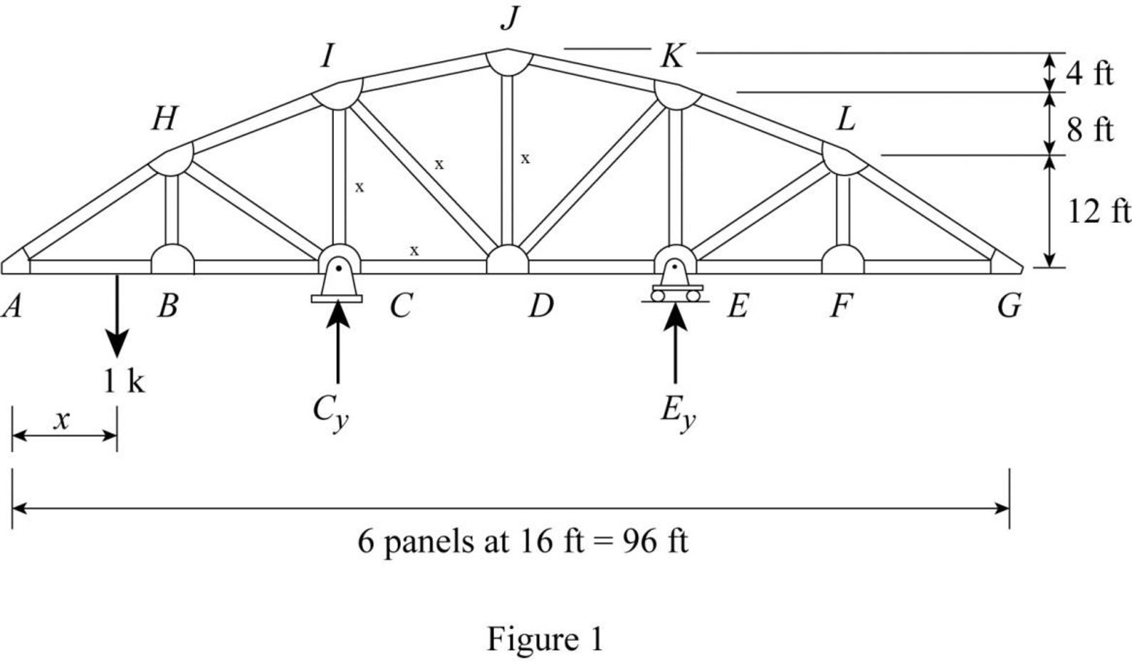
Refer Figure 1,
Find the reaction at C and E when 1 k load placed from A to G. (0≤x≤96 ft).
Apply moment equilibrium at C.
ΣMC=0−1(32−x)−Ey(32)=032Ey=−(32−x)32Ey=x−32Ey=x32−1
Apply force equilibrium equation along vertical.
Consider the upward force as positive (↑+) and downward force as negative (↓−).
ΣFy=0Cy+Ey−1=0Cy+x32−1=1Cy=2−x32
Influence line for the force in member CD.
The expressions for the member force FCD can be determined by passing an imaginary section aa through the members HI, CI, and CD and then apply a moment equilibrium at I.
Draw the free body diagram of the section as shown in Figure 2.
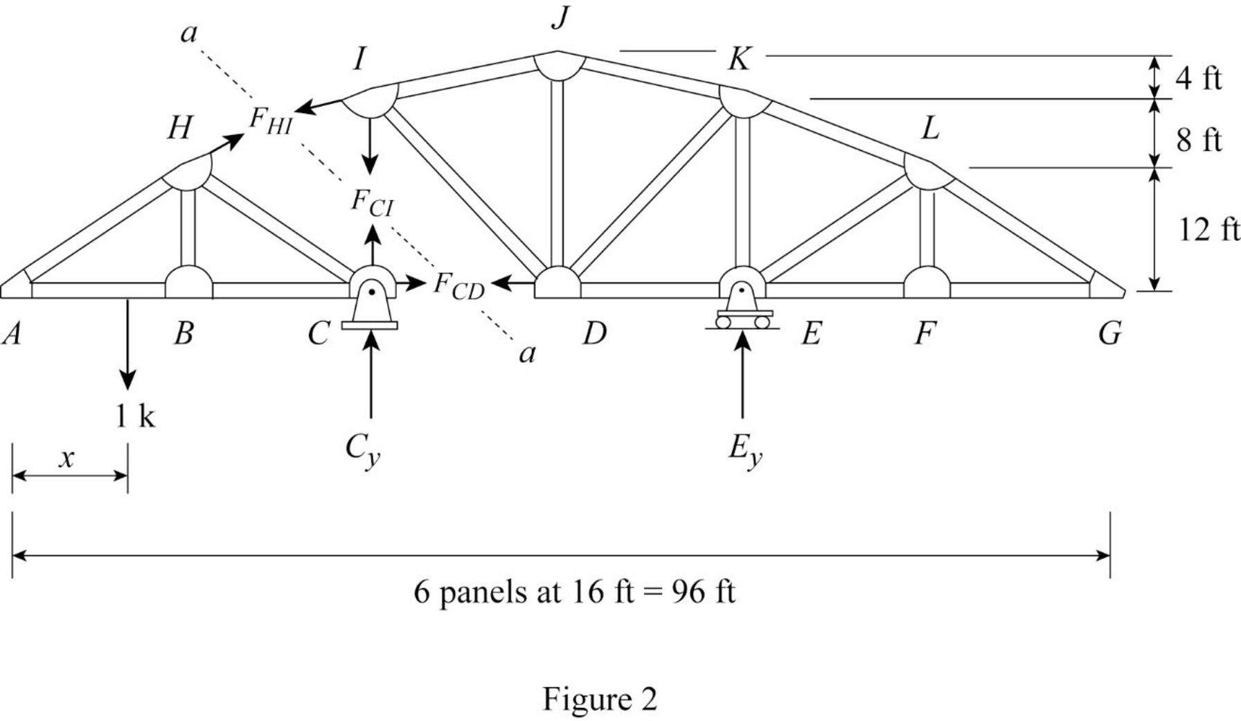
Refer Figure 2.
Apply 1 k load just the left of C (0≤x≤32 ft)
Find the equation of member force CD from A to C.
Consider the section DG.
Apply moment equilibrium equation at I.
Consider clockwise moment as negative and anticlockwise moment as positive.
ΣMI=0
−FCD(20)+Ey(32)=020FCD=32EyFCD=85Ey
Substitute x32−1 for Ey.
FCD=85(x32−1)=x20−85
Apply 1 k load just the right of C (32 ft≤x≤96 ft).
Find the equation of member force CD from C to G.
Consider the section AC.
Apply moment equilibrium equation at I.
Consider clockwise moment as positive and anticlockwise moment as negative.
ΣMI=0
FCD(20)=0FCD=0
Thus, the equation of force in the member CD,
FCD=x20−85,0≤x≤32 ft (1)
FCD=0,32 ft≤x≤96 ft (2)
Find the force in member CD using the Equation (1) and (2) and then summarize the value in Table 1.
| x (ft) | Apply 1 k load | Force in member CD (k) | Influence line ordinate for the force in member CD (k/k) |
| 0 | A | x20−85=020−85=−1.6 | −1.6 |
| 16 | B | x20−85=1620−85=−0.8 | −0.8 |
| 32 | C | 0 | 0 |
| 48 | D | 0 | 0 |
| 64 | E | 0 | 0 |
| 80 | F | 0 | 0 |
| 96 | G | 0 | 0 |
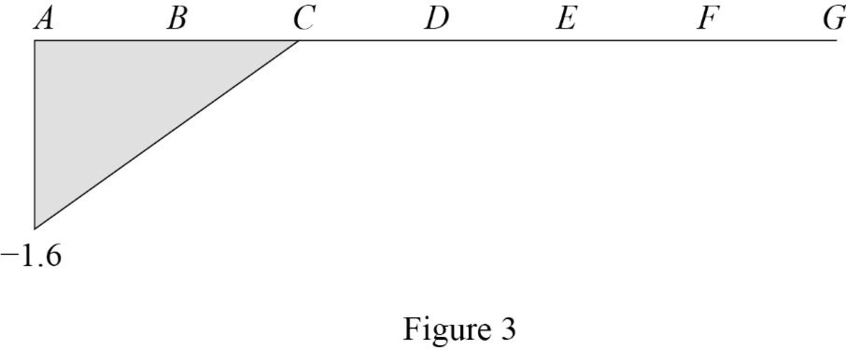
Sketch the influence line diagram for ordinate for the force in member CD using Table 1 as shown in Figure 3.
Influence line for the force in member CI.
Refer Figure 2.
Apply 1 k load just the left of C (0≤x≤32 ft).
Find the equation of member force CI from A to C.
Consider the section AC.
Apply moment equilibrium equation at H.
Consider clockwise moment as negative and anticlockwise moment as positive.
ΣMH=0Cy(16)+FCD(12)+FCI(16)+1(16−x)=016FCI=−16Cy−12FCD−(16−x)FCI=−1616Cy−1216FCD−1616+x16FCI=−Cy−34FCD−1+x16
Substitute 2−x32 for Cy and x20−85 for FCD.
FCI=−(2−x32)−34(x20−85)−1+x16=−2+x32−3x80+65−1+x16=9x160−1.8
Apply 1 k load just the right of C (32 ft≤x≤96 ft)
Find the equation of member force CI from C to G.
Consider the section AC.
Apply moment equilibrium equation at H.
Consider clockwise moment as positive and anticlockwise moment as negative.
ΣMH=0Cy(16)+FCD(12)+FCI(16)=016FCI=−16Cy−12FCDFCI=−1616Cy−1216FCDFCI=−Cy−34FCD
Substitute 2−x32 for Cy and 0 for FCD.
FCI=−(2−x32)−34(0)=−2+x32=x32−2
Thus, the equation of force in the member CI,
FCI=9x160−1.8,0≤x≤32 ft (3)
FCI=x32−2,32 ft<x≤96 ft (4)
Find the force in member CI using the Equation (1) and (2) and then summarize the value in Table 2.
| x (ft | Apply 1 k load | Force in member CI (k) | Influence line ordinate for the force in member CI (k/k) |
| 0 | A | 9x160−1.8=9(0)160−1.8=−1.8 | −1.8 |
| 16 | B | 9x160−1.8=9(16)160−1.8=−0.9 | −0.9 |
| 32 | C | 9x160−1.8=9(32)160−1.8=0 | 0 |
| 48 | D | x32−2=4832−2=−0.5 | −0.5 |
| 64 | E | x32−2=6432−2=0 | 0 |
| 80 | F | x32−2=8032−2=0.50 | 0.5 |
| 96 | G | x32−2=9632−2=1 | 1 |
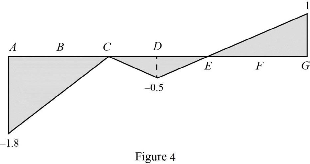
Sketch the influence line diagram for ordinate for the force in member CI using Table 2 as shown in Figure 4.
Influence line for the force in member DI.
The expressions for the member force FDI can be determined by passing an imaginary section bb through the members IJ, DI and CD and then apply a moment equilibrium at J.
Draw the free body diagram of the section bb as shown in Figure 5.
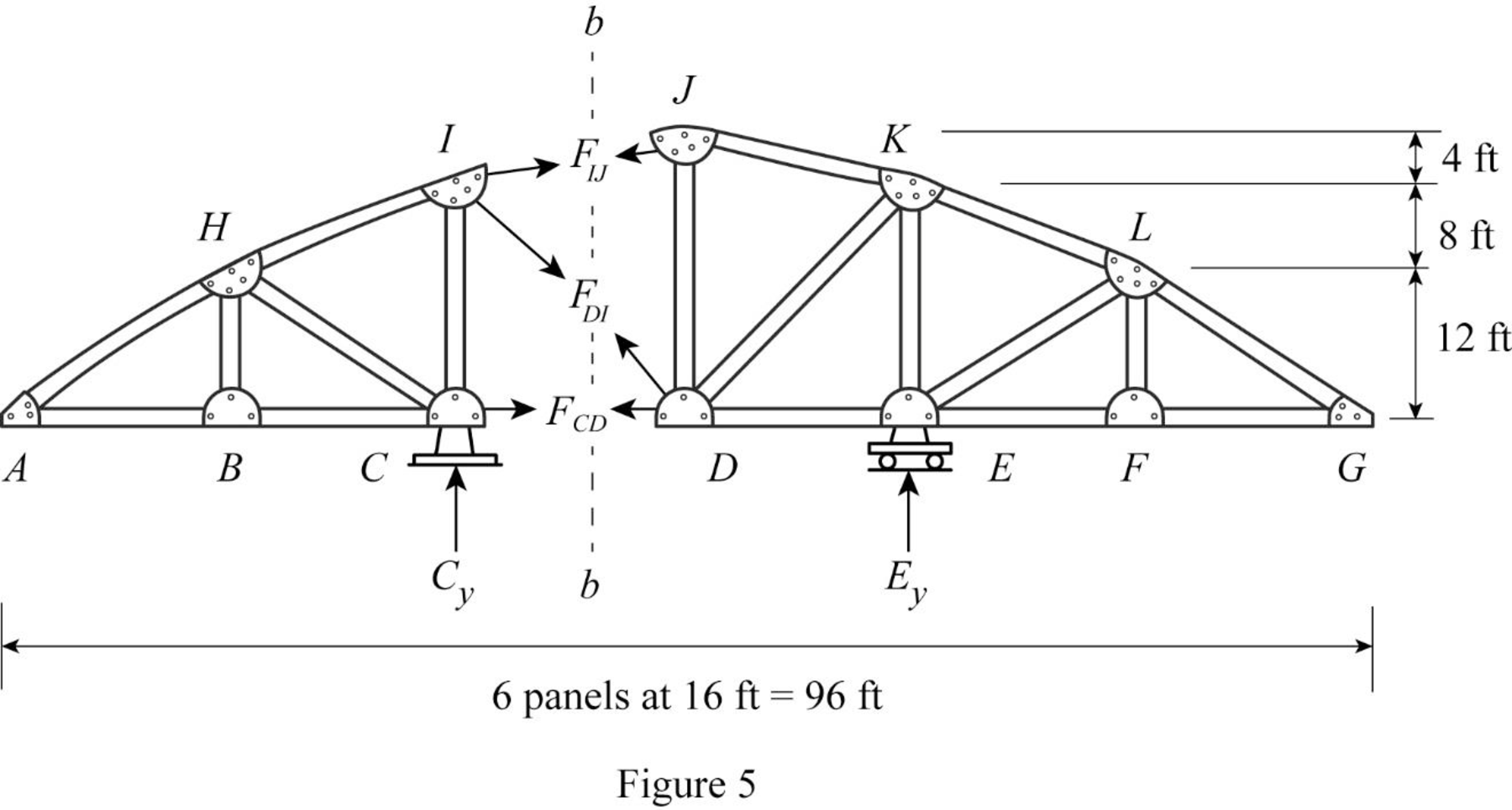
Refer Figure 5.
Apply 1 k load just the left of C (0≤x≤32 ft).
Find the equation of member force DI from A to C.
Consider the section DG.
Apply moment equilibrium equation at J.
Consider clockwise moment as negative and anticlockwise moment as positive.
ΣMJ=0Ey(16)−FCD(24)−(16√162+202)FDI(24)=015FDI=16Ey−24FCDFDI=1615Ey−1.6FCD
Substitute x20−85 for FCD and x32−1 for Ey.
FDI=1615(x32−1)−1.6(x20−85)=x30−1615−2x25+6425=11275−7x150
Apply 1 k load just the right of C (32 ft≤x≤96 ft).
Find the equation of member force DI from C to G.
Consider the section AC.
Apply moment equilibrium equation at J.
Consider clockwise moment as positive and anticlockwise moment as negative.
ΣMJ=0Cy(16)−FCD(24)−20√162+202FDI(16)−16√162+202FDI(4)=012.5FDI+2.5FDI=16Cy−24FCD15FDI=16Cy−24FCDFDI=1615Cy−2415FCD
Substitute 2−x32 for Cy and 0 for FCD.
FDI=1615(2−x32)−2415(0)=3215−x30
Thus, the equation of force in the member DI,
FDI=11275−7x150,0≤x≤32 ft (5)
FDI=3215−x30,32 ft≤x≤96 ft (6)
Find the force in member DI using the Equation (5) and (6) and then summarize the value in Table 3.
| x (ft) | Apply 1 k load | Force in member DI (k) | Influence line ordinate for the force in member DI (k/k) |
| 0 | A | 11275−7x150=11275−7(0)150=1.494 | 1.494 |
| 16 | B | 11275−7x150=11275−7(16)150=0.747 | 0.747 |
| 32 | C | 11275−7x150=11275−7(32)150=0 | 0 |
| 48 | D | 3215−x30=3215−4830=0.534 | 0.534 |
| 64 | E | 0 | 0 |
| 80 | F | 3215−x30=3215−8030=−0.5340 | −0.534 |
| 96 | G | 3215−x30=3215−9630=−1.067 | −1.067 |
Sketch the influence line diagram for ordinate for the force in member DI using Table 3 as shown in Figure 6.

Influence line for the force in member DJ.
The expressions for the member force FDJ can be determined by passing an imaginary section cc through the members JK, DJ, DI, and CD and then apply a moment equilibrium at K.
Draw the free body diagram of the section cc as shown in Figure 7.
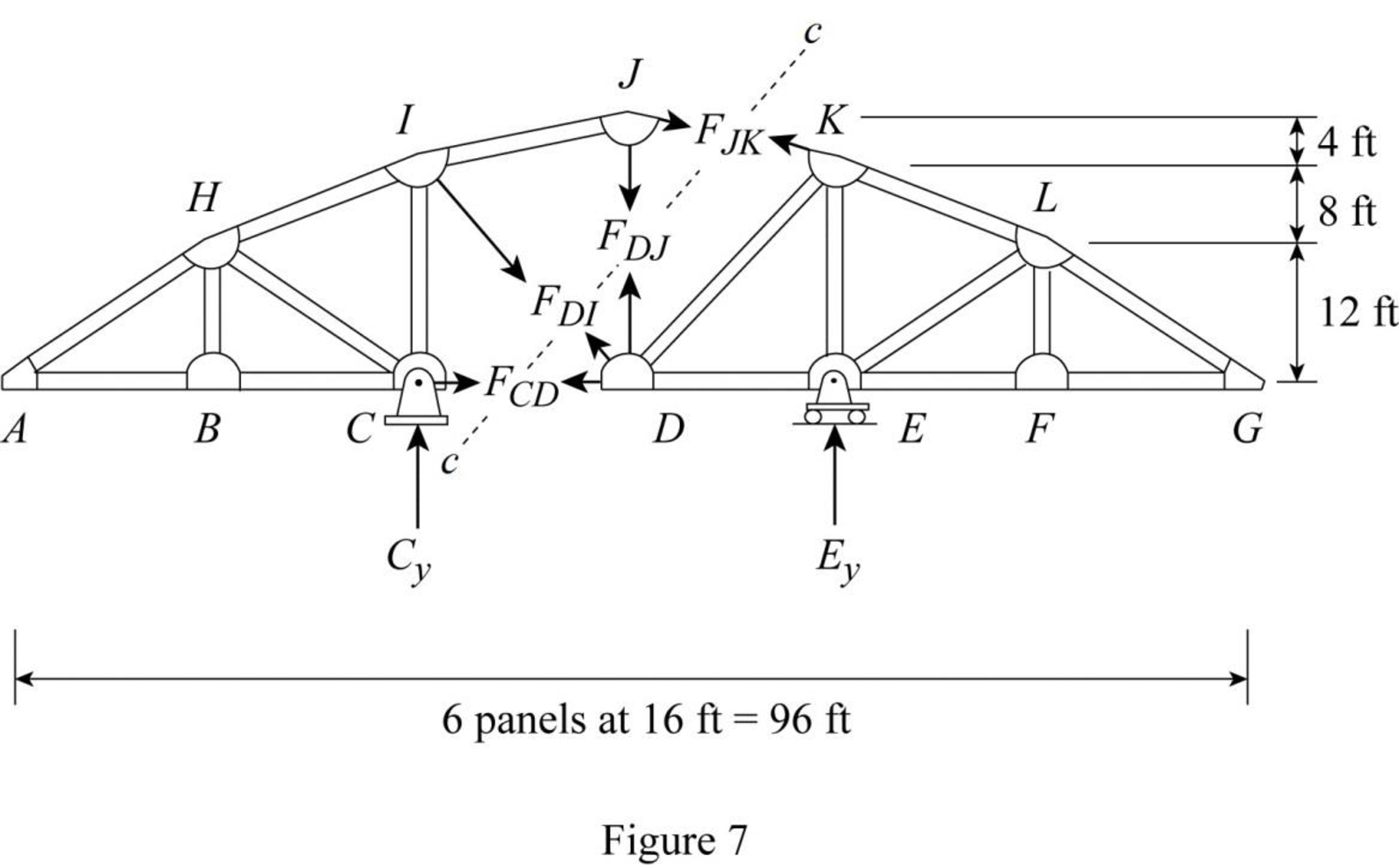
Refer Figure 7.
Apply 1 k load just the left of C (0≤x≤32 ft)
Find the equation of member force DJ from A to C.
Consider the section DG.
Apply moment equilibrium equation at C.
The member force DI is resolved in horizontal and vertical.
Consider clockwise moment as positive and anticlockwise moment as negative.
ΣMK=0FCD(20)+16√162+202FDI(20)+20√162+202FDI(16)+FDJ(16)=020FCD+12.494FDI+12.494FDI+16FDJ=016FDJ=−20FCD−25FDIFDJ=−1.25FCD−1.5625FDI
Substitute x20−85 for FCD and 11275−7x150 for FDI.
FDJ=−1.25(x20−85)−1.5625(11275−7x150)=−0.0625x+2−2.333+0.07292x=0.0104x−0.333
Apply 1 k load just the right of C (32 ft≤x≤96 ft).
Find the equation of member force DJ from C to G.
Consider the section DG.
Apply moment equilibrium equation at K.
The member force DI is resolved in horizontal and vertical.
Consider clockwise moment as positive and anticlockwise moment as negative.
ΣMK=0−FCD(20)−20√162+202FDI(32)−FDJ(16)+Cy(32)=0−20FCD−25FDI−16FDJ+32Cy=0
Substitute 0 for FCD, 3215−x30 for FDI, and 2−x32 for Cy.
−20(0)−25(3215−x30)−16FDJ+32(2−x32)=00−53.333+0.833x−16FDJ+64−x=010.667−0.167x−16FDJ=016FDJ=10.667−0.167xFDJ=0.667−0.0104x
Thus, the equation of force in the member DJ,
FDJ=0.0104x−0.333,0≤x≤32 ft (7)
FDJ=0.0104x−0.667,32 ft≤x≤96 ft (8)
Find the force in member DJ using the Equation (7) and (8) and then summarize the value in Table 4.
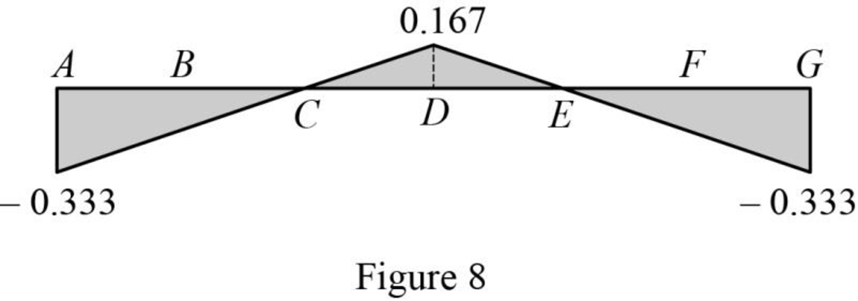
| x (ft) | Apply 1 k load | Force in member DJ (k) | Influence line ordinate for the force in member DJ (k/k) |
| 0 | A | 0.0104(0)−0.333=−0.333 | −0.333 |
| 16 | B | 0.0104(16)−0.333=−0.167 | −0.167 |
| 32 | C | 0.0104(32)−0.333=0 | 0 |
| 48 | D | 0.0104(48)−0.667=0.167 | 0.167 |
| 64 | E | 0.667−0.0104(64)=0 | 0 |
| 80 | F | 0.667−0.0104(80)=−0.167 | −0.167 |
| 96 | G | 0.667−0.0104(96)=−0.333 | −0.333 |
Sketch the influence line diagram for ordinate for the force in member DJ using Table 4 as shown in Figure 8.
Want to see more full solutions like this?
Chapter 8 Solutions
Structural Analysis, Si Edition (mindtap Course List)


- 2nd monthly 4th. Year- exam Hydraulic Structures 9/12/201 QL Check the floor thickness the cutoff depths and the horizontal floor length for the given regulator using Lane's method. u/s. W.L. u/s. B.L 24.25 = 20.50 m x Discharge Q = 60 m³/s Waterway S = Duis 3.5 m 10 m Distance from u/s pile line Cd = 0.9 C = 6.5 Concrete floor thickness. D/S.W.L.. D/S. B.L. 24.00 th = 19.65 m u/s. canal bed width = 15 m Horizontal floor length L₁ = 51 m D 6m to the gate silt factor f under the gate 9.0m = 0.7 beginning' · of floor. at at end 2.4 ton / m³ 3m 1 = m I m Fronc Q.2. What is the function of 0 u/s cutoff 4 Fish ladder ③ D/S cutoff Lock The flow net Intermediate oile Al-Mansour University College U/S guid bankarrow_forwardFor the portal frame determine the reactions at a using the approximate method if all supports are fixed.arrow_forwardPlease answer the question in the picture.arrow_forward
- Please answer the question in the picture. Thank you so much for your help!arrow_forwardI dont understand how to do the hand calculations help pls A multi-cell box beam, 1800 mm long, is subject to a vertical shear load of 6 kN applied in a vertical plane. Points 1-8 mark the boom elements on the beam. Calculate the shear flow in each web and locate the shear centre using hand calculations. The results, including mesh convergence, shear flow, stress distribution, deformation, and shear centre location, will then be compared with findings from Abaqus FEA. The material properties are: Young's modulus (E) is 72 GPa, and Poisson's ratio (ν) is 0.3.arrow_forwardfind the following (show all work) Seepage velocity vs (m/sec) Discharge velocity v (m/sec) Hydraulic Conductivity k (m/sec) given : length of specimen 0.25 m , Diameter of specimen 0.10 m , Head difference 0.50 m , water collected in 2 minutes, 50 ml, the void ratio of soil 0.46arrow_forward
- draw sketches to comment the different components of the total head (Bernoulli's equation) Define head loss Explain the differences between a seepage and a discharge velocities in soil. Are they related if so in what way.arrow_forwardQ1: Determine the duration of project for the activities shown below, and find the critical path by using (A-0- Diagram) ABC DEFOHIJKMN R 4 5 6 8 3 7 8 11 3 8 3 7 8 11 3 8 489 4 Activity Duration (Weeks) Followed C,D D,F JJHOK MIK NMR- by E 1arrow_forwardI dont understand how to do the hand calculations help pls A multi-cell box beam, 1800 mm long, is subject to a vertical shear load of 6 kN applied in a vertical plane. Points 1-8 mark the boom elements on the beam. Calculate the shear flow in each web and locate the shear centre using hand calculations. The results, including mesh convergence, shear flow, stress distribution, deformation, and shear centre location, will then be compared with findings from Abaqus FEA. The material properties are: Young's modulus (E) is 72 GPa, and Poisson's ratio (ν) is 0.3.arrow_forward
- 2. Vertical highway curve: Given PVI at 65 + 00, L = 800 ft, g1 = +4%, g2 = -3%, and PVI elevation = 264.2 ft, compute the elevations of the curve high point and for all of the full stations until reaching the end of the curve as well as for the beginning and end of the curve.arrow_forward1. Horizontal highway curve: Given Pl at 65 + 78.20, A = 22°00', and D = 6°00', compute the deflections to the nearest second for the full stations (means stations 65+00, 66+00, etc.) as well as for the beginning and end of the curve.arrow_forwardWater flows uniformly in a channel with a bottom slope of 0.002 and a compound cross-section: Section 1 has concrete sides and bottom. Section 2 is vegetated with light brush. Manning coefficients and dimensions (in meters) are shown below: Calculate: a. The composite Manning roughness coefficient for the channel b. The flow rate in cubic meters per second (cms) for the water levels shownarrow_forward
