
Concept explainers
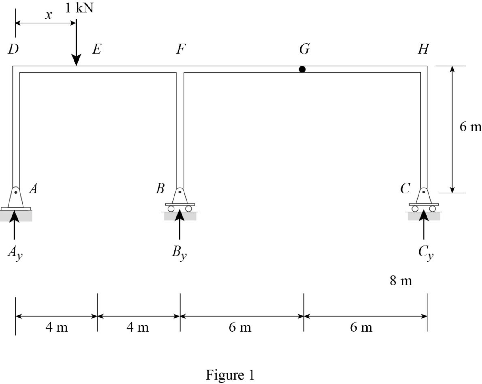
Draw the influence lines for the vertical reactions at supports A, B, C and the shear and bending moment at point E.
Explanation of Solution
Calculation:
Apply a 1 kN unit moving load at a distance of x from left end D.
Sketch the free body diagram of frame as shown in Figure 1.
Influence line for vertical reaction at supports C.
Refer Figure 1.
Find the equation of vertical reaction at supports C.
Apply 1 kN load just left of G
Consider section GH.
Take moment at G from C.
Consider clockwise moment as positive and anticlockwise moment as negative.
Apply 1 kN load just right of G
Consider section GH.
Take moment at G from C.
Consider clockwise moment as positive and anticlockwise moment as negative.
Thus, the equation of vertical reaction at supports C as follows,
Find the influence line ordinate of
Substitute 20 m for
Thus, the influence line ordinate of
Similarly calculate the influence line ordinate of
| x (m) | Points | Influence line ordinate of |
| 0 | D | 0 |
| 4 | E | 0 |
| 8 | F | 0 |
| 14 | G | 0 |
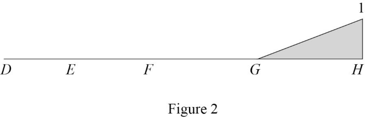
| 20 | H | 1 |
Sketch the influence line diagram for vertical reaction at supports C using Table 1 as shown in Figure 2.
Influence line for vertical reaction at support A.
Apply 1 kN load just left of F
Refer Figure 1.
Find the equation of vertical reaction at supports C.
Consider section DF.
Take moment at B from A.
Consider clockwise moment as positive and anticlockwise moment as negative.
Apply 1 kN load just right of F.
Consider section FH.
Consider moment at B from A is equal to from C.
Consider clockwise moment as positive and anticlockwise moment as negative.
Find the equation of vertical reaction at A from F to G
Substitute 0 for
Find the equation of vertical reaction at A from G to H
Substitute
Thus, the equation of vertical reaction at supports A as follows,
Find the influence line ordinate of
Substitute 14 m for
Thus, the influence line ordinate of
Similarly calculate the influence line ordinate of
| x (m) | Points | Influence line ordinate of |
| 0 | D | 1 |
| 4 | E | 0.5 |
| 8 | F | 0 |
| 14 | G | |
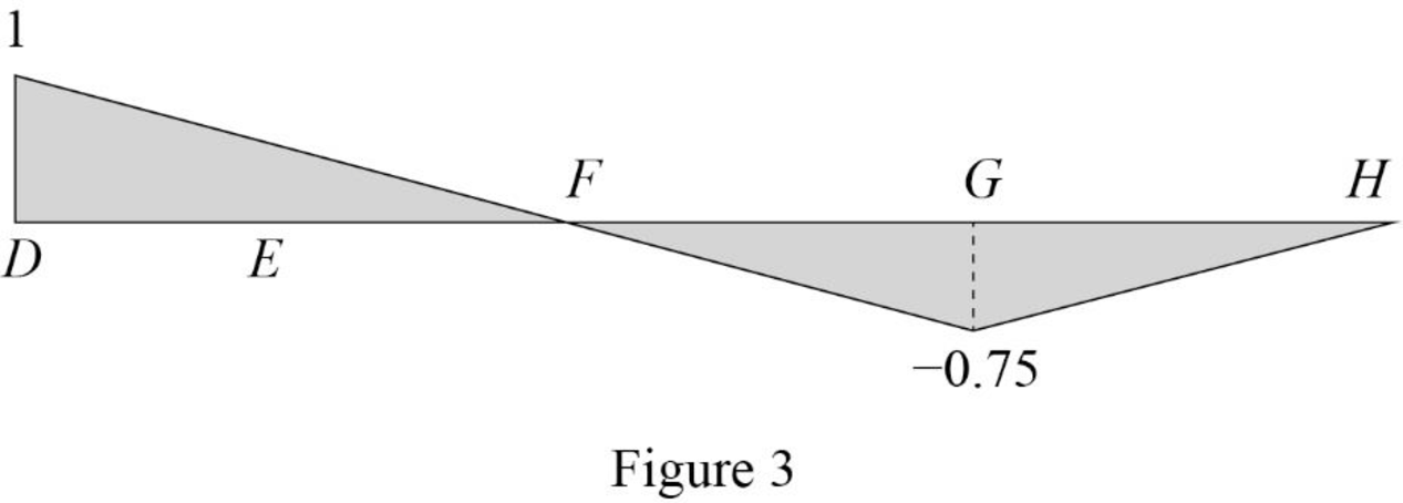
| 20 | H | 0 |
Sketch the influence line diagram for the vertical reaction at support A using Table 2 as shown in Figure 3.
Influence line for vertical reaction at support B.
Apply a 1 kN unit moving load at a distance of x from left end C.
Refer Figure 1.
Apply vertical equilibrium in the system.
Consider upward force as positive and downward force as negative.
Find the equation of vertical support reaction
Substitute
Find the equation of vertical support reaction
Substitute
Thus, the equation of vertical support reaction at B as follows,
Find the influence line ordinate of
Substitute 8 m for
Thus, the influence line ordinate of
Similarly calculate the influence line ordinate of
| x (m) | Points | Influence line ordinate of |
| 0 | D | 0 |
| 4 | E | 0.5 |
| 8 | F | 1 |
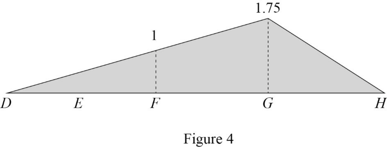
| 14 | G | 1.75 |
| 20 | H | 0 |
Sketch the influence line diagram for the vertical reaction at support B using Table 3 as shown in Figure 4.
Influence line for shear at point E.
Find the equation of shear
Apply 1 kN just left of E.
Consider section DE.
Sketch the free body diagram of the section AD as shown in Figure 5.
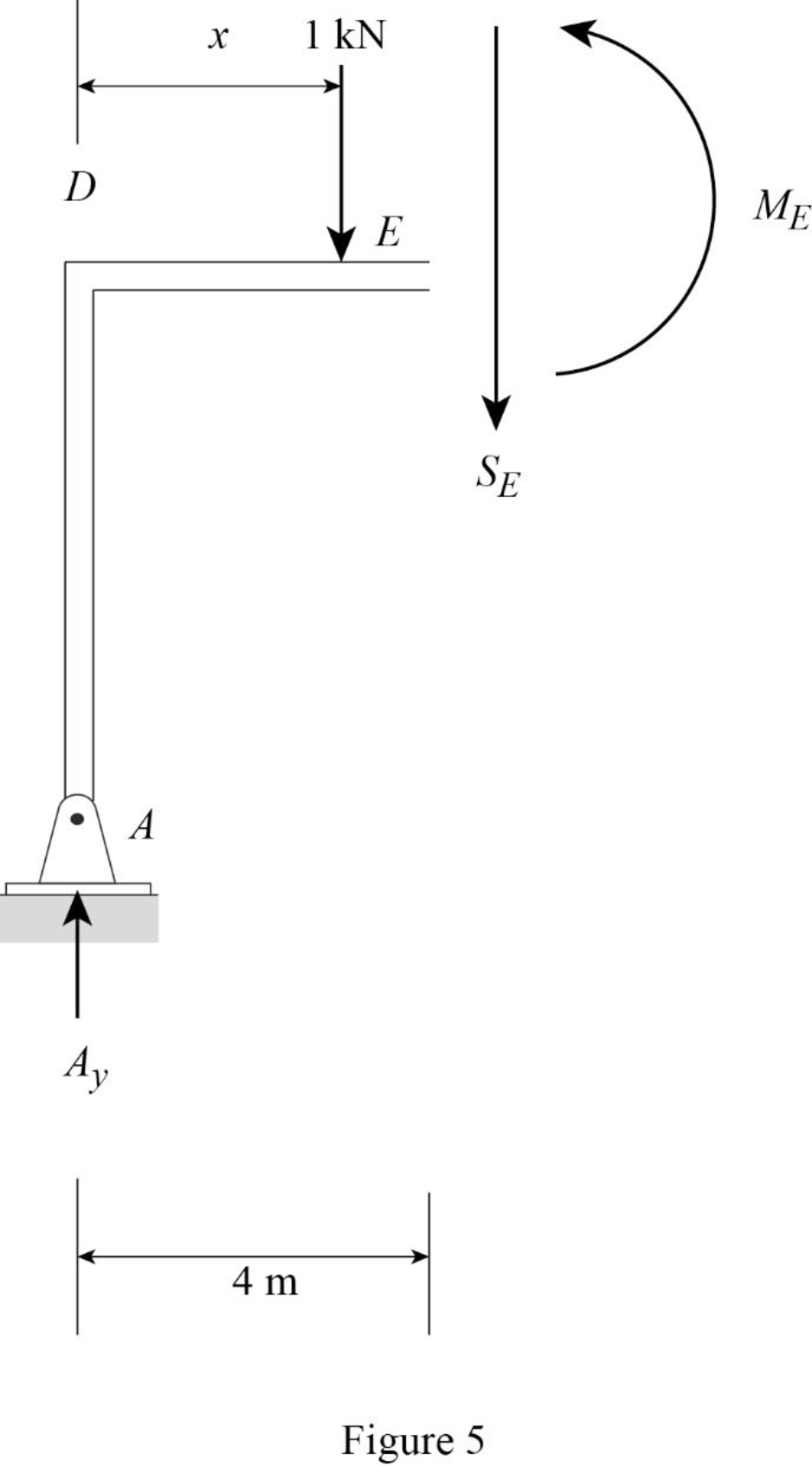
Refer Figure 5.
Apply equilibrium equation of forces.
Consider upward force as positive
Find the equation of shear force at E of portion DE
Substitute
Find the equation of shear
Apply 1 kN just right of E.
Consider section DE.
Sketch the free body diagram of the section DE as shown in Figure 6.
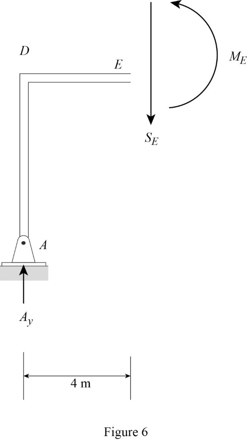
Refer Figure 6.
Apply equilibrium equation of forces.
Consider upward force as positive
Find the equation of shear force at E of portion EG
Substitute
Find the equation of shear force at E of portion GH
Substitute
Thus, the equations of the influence line for
Find the influence line ordinate of
Substitute 4 m for
Thus, the influence line ordinate of
Find the shear force of
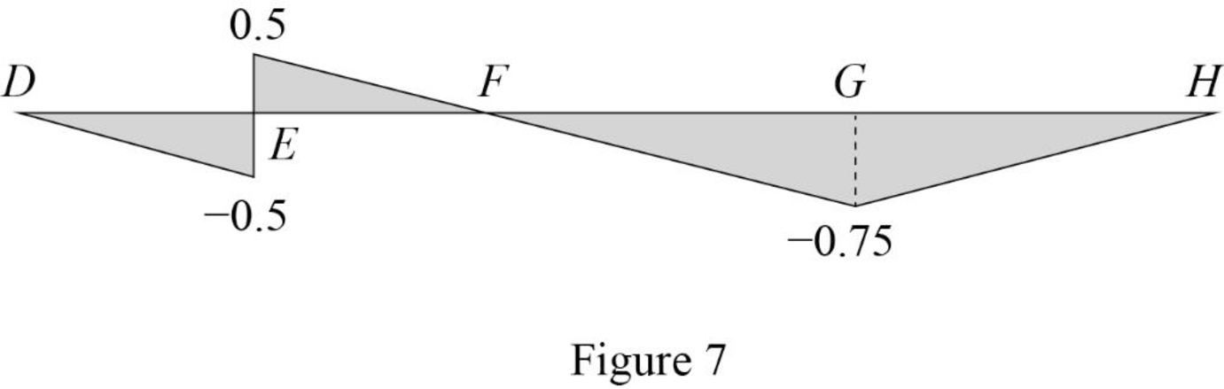
| x (m) | Points | Influence line ordinate of |
| 0 | D | 0 |
| 4 | ||
| 4 | ||
| 8 | F | 0 |
| 14 | G | |
| 20 | H | 0 |
Draw the influence lines for the shear force at point E using Table 4 as shown in Figure 7.
Influence line for moment at point E.
Refer Figure 5.
Consider section DE.
Consider clockwise moment as positive and anticlockwise moment as negative.
Take moment at E.
Find the equation of moment at E of portion DE
Substitute
Refer Figure 6.
Consider section DE.
Find the equation of moment at E of portion EH
Consider clockwise moment as positive and anticlockwise moment as negative.
Take moment at E.
Find the equation of moment at E of portion EF.
Find the equation of moment at E of portion EG
Substitute
Find the equation of moment at E of portion GH
Substitute
Thus, the equations of the influence line for
Find the influence line ordinate of
Substitute 4 m for
Thus, the influence line ordinate of
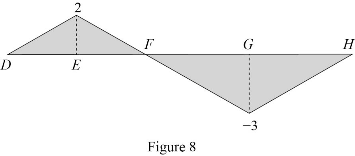
Find the moment at various points of x using the Equations (15), (16), and (17) and summarize the value as in Table 5.
| x (m) | Points | Influence line ordinate of |
| 0 | D | 0 |
| 4 | E | 2 |
| 8 | F | 0 |
| 14 | G | |
| 20 | H | 0 |
Draw the influence lines for the moment at point E using Table 5 as shown in Figure 8.
Therefore, the influence lines for the vertical reactions at supports A, B, and C and the influence lines for the shear and bending moment at point E are drawn.
Want to see more full solutions like this?
Chapter 8 Solutions
EBK STRUCTURAL ANALYSIS


- 6-21 Four 3×3× 1/4 angles are used to form the member shown in the accompanying illustration. The member is 24 ft long, has pinned ends, and consists of A572-Grade 50 steel. Determine the LRFD design strength and the ASD allowable strength of the member. Design single lacing and end tie plates, assuming connections are made to the angles with 3/4-in diameter bolts. (Ans. 159.1 k LRFD; 106.0 k ASD) Figure P6-21 12 in L 12 inarrow_forward1000 th 2' 2' w=200 to /ft Handout Problem #3. A beam has the loading and cross section shown. 1) Draw the shear force and bending moment diagrams for the beam. 5" 2) Determine the maximum bending stress in the beam. Carefully identify its location both along the beam and along the cross section. 3) Determine the maximum transverse shear stress in the beam. Carefully identify its location both along the beam and along the cross section: y=2" up from bottom "INA = 33.33 int VMAX = 1160+b MMAX - 2704 Hb-ft QMAX = 8mm³arrow_forwardUnits: lb-ft Handout Problem #2 The dimensions of the shape as well as the bending moment diagram of a flanged wooden shape are shown. Determine: (a) the maximum tensile bending stress at any location along the beam and (b) the maximum compressive bending stress at any location along the beam. 10 in. 10,580 9,200 4,743 2 in. 8 in. 2 in. 2 in. -8,400 6 in.arrow_forward
- (USE 0BC 2024) For a 800 m2 4-storey sprinklered Dry-cleaning establishment (not using explosive solvents), facing 1 street(s), what are the minimum required fire-resistance ratings (FRR) or fire-protection ratings (FPR) for the following? Typical floor assembly (in minutes, please. Just write the number of minutes please) Detailed OBC reference = Public corridor wall (in minutes please) Detailed OBC reference = Suite egress door (in minutes, please) = Detailed OBC reference = Exit stair walls (in minutes, please) = Detailed OBC reference = Exit stair door (in minutes, please) = Detailed OBC reference = Elevator shaft enclosure (in minutes, please) = Detailed OBC reference = Vertical mechanical shaft enclosure (in minutes, please) = Detailed OBC reference =arrow_forwardQuestion 6 options: The fourth storey of this "Dry-cleaning establishment (not using flammable solvents)" building measures 41 m x 19 m and has a public corridor. Determine the following dimensions, in millimetres (mm) The minimum width of its ramp, if it is sloped at 6°. Please give your answer to the nearest millimetre. The minimum width of its egress doors for Suite D (measuring 6 m × 4 m, ignored the elevator). Please give your answer to the nearest millimetre. The minimum width of its corridor. Please give your answer to the nearest millimetre. The minimum width of its ramp, if it is sloped at 13°. Please give your answer to the nearest millimetre.arrow_forwardFor the exposing building face marked (XX) of this unsprinklered 'Beauty parlours' building, please determine the following. justify THE answer in your hand-written solution.arrow_forward
- If the angle for the sloped glazing below is 45°, is it considered part of the roof or part of the wall? justify the answer with appropriate and detailed OBC references.arrow_forwardDetermine the state of stress acting at point E. Show the results on a differential elementat this point.arrow_forwardConsider the structure shown in the following figure, which includes two identical towers, a main cable whose unstretched length is 110 m handing between them, and two side cables with negligible weights (so that they can be modeled as massless springs). The side cables are pretentioned so that the net horizontal force on a tower iszero. The mass per unit length of the main cable is 10 kg/m and EAo = 1000KN. Thehorizontal distance between the two towers is 100 m. The angle del is 60°. By design the total horizontal load on each tower is zero. Find A)The horizontal and vertical loads exerted on each tower by the main cable B)The minimum mass M of the counter weights. Note that the counter weights are blocked from moving in the horizontal directionarrow_forward
- 4th Order Rurka-Kutta Method This assignment will expand your skills on using Excel to perform some numerical analyses and plot your results. It is a means to familiarize you more with basic features in the spreadsheet. Preliminaries: a. Start a new file called R-K.xlsx (for this exercise, you may use the work you did in class but please be careful not to delete what you already have) b. Plan ahead Exercise 1: Using the 4" Order Ruga-Kutta Method that we recently learned, evaluate the following ordinary differential equation (ODE): dx f(t, x) = = x+t² dt At the initial position, X= 0, the time is = 0.1 minutes. Using a step size of, h = 0.05, what is the time spent to reach a position that is equal to 17 (Hint: use a O and b 1) Exercise 2 Using the 4th Order Ruga-Kutta Method, solve the following problem: The concentration of a certain non-reactive (conservative) chemical is given as a function of time by: de f(t,c) = = 30-3c Where c is the concentration and t is time. At the initial…arrow_forwardWhat percentage of all communication is screened out or changed by the receiver?”arrow_forwardIn testing a certain kind or truck tire over rugged terrain, it is found that 20% of the trucks fail to complete the test run without a blowout. Of the next 13 trucks tested, find the probability that (a) from 2 to 6 have blowouts, (b) fewer than 4 have blowouts, and (c) more than 5 have blowouts. Click here to view page 1 of the table of binomial probability sums. Click here to view page 2 of the table of binomial probability sums. (a) The probability that from 2 to 6 trucks have blowouts is (Round to four decimal places as needed.)arrow_forward
