
PEARSON ETEXT ENGINEERING MECH & STATS
15th Edition
ISBN: 9780137514724
Author: HIBBELER
Publisher: PEARSON
expand_more
expand_more
format_list_bulleted
Concept explainers
Videos
Textbook Question
Chapter 8, Problem 126P
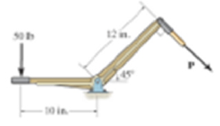
The bell crank fits loosely into a 0.5-in-diameter pin. Determine the required force P which is just sufficient to rotate the bell crank clockwise. The coefficient of static fraction between the pin and the bell crank is, μx = 0.3.
Expert Solution & Answer
Want to see the full answer?
Check out a sample textbook solution
Students have asked these similar questions
Assume multiple single degree of freedom systems with natural periods T ∈ [0.05, 2.00] seconds with in-crement of period dT = 0.05 seconds. Assume three cases of damping ratio: Case (A) ξ = 0%; Case (B)ξ = 2%; Case (C) ξ = 5%. The systems are initially at rest. Thus, the initial conditions are u(t = 0) = 0 anḋu(t = 0) = 0. The systems are subjected to the base acceleration that was provided in the ElCentro.txt file(i.e., first column). For the systems in Case (A), Case (B), and Case (C) and for each natural period computethe peak acceleration, peak velocity, and peak displacement responses to the given base excitation. Please,use the Newmark method for β = 1/4 (average acceleration) to compute the responses. Create threeplots with three lines in each plot. The first plot will have the peak accelerations in y-axis and the naturalperiod of the system in x-axis. The second plot will have the peak velocities in y-axis and the natural periodof the system in x-axis. The third plot will have…
Both portions of the rod ABC are made of an aluminum for which E = 70 GPa.
Based on the given information find:
1- deformation at A
2- stress in BC
3- Total strain
4- If v (Poisson ratio is 0.25, find the
lateral deformation of AB
Last 3 student ID+ 300 mm=L2
724
A
P=Last 2 student ID+ 300 KN
24
24
Diameter Last 2 student ID+ 15 mm
Last 3 student ID+ 500 mm=L1
724
C
B
24
Q=Last 2 student ID+ 100 KN
24
Diameter Last 2 student ID+ 40 mm
Q2Two wooden members of uniform cross section are joined by the simple scarf splice shown. Knowing that the
maximum allowable tensile stress in the glued splice is 75 psi, determine (a) the largest load P that can be safely
supported, (b) the corresponding shearing stress in the splice.
น
Last 1 student ID+5 inch=W
=9
4
L=Last 1 student ID+8 inch
=12
60°
P'
Chapter 8 Solutions
PEARSON ETEXT ENGINEERING MECH & STATS
Ch. 8 - F81. Determine the friction developed between the...Ch. 8 - F82. Determine the minimum force P to prevent the...Ch. 8 - Prob. 3FPCh. 8 - F84. If the coefficient of static friction at...Ch. 8 - F85. Determine the maximum force P that can be...Ch. 8 - F86. Determine the minimum coefficient of static...Ch. 8 - F87. Blocks A, B, and C have weights of 50 N, 25...Ch. 8 - F88. If the coefficient of static friction at all...Ch. 8 - Prob. 9FPCh. 8 - Determine the maximum force P the connection can...
Ch. 8 - The mine car and its contents have a total mass of...Ch. 8 - Prob. 4PCh. 8 - The automobile has a mass of 2 Mg and center of...Ch. 8 - The automobile has a mass of 2 Mg and canter of...Ch. 8 - Prob. 9PCh. 8 - Determine the angle at which the applied force P...Ch. 8 - Prob. 12PCh. 8 - The car has a mass of 1.6 Mg and center of mass at...Ch. 8 - The log has a coefficient of state friction of, s...Ch. 8 - The spool of wire having a weight of 300 Ib rests...Ch. 8 - The spool of wire having a weight of 300 Ib rests...Ch. 8 - Prob. 20PCh. 8 - The uniform thin pole has a weight of 30 Ib and a...Ch. 8 - The uniform pole has a weight of 30 Ib and a...Ch. 8 - The friction pawl is pinned at A and rests against...Ch. 8 - Two blocks A and B have a weight of 10 Ib and 6...Ch. 8 - Two blocks A and B have a weight of 10 Ib and 6...Ch. 8 - Determine the smallest force P that must be...Ch. 8 - The man having a weight of 200 Ib pushes...Ch. 8 - The uniform hoop of weight W is subjected to the...Ch. 8 - Determine the maximum horizontal force P that can...Ch. 8 - Determine the minimum force P needed to push the...Ch. 8 - Prob. 41PCh. 8 - Prob. 42PCh. 8 - Prob. 51PCh. 8 - Prob. 52PCh. 8 - Determine the smallest couple moment that can be...Ch. 8 - If P=250 N, determine the required minimum...Ch. 8 - Determine the minimum applied force P required to...Ch. 8 - Prob. 67PCh. 8 - Prob. 68PCh. 8 - Prob. 71PCh. 8 - Prob. 72PCh. 8 - Prob. 73PCh. 8 - Prob. 74PCh. 8 - Prob. 81PCh. 8 - Determine the horizontal force P that must be...Ch. 8 - A 180-lb farmer tries to restrain the cow from...Ch. 8 - The 100-lb boy at A is suspended from the cable...Ch. 8 - Prob. 87PCh. 8 - Determine the force P that must be applied to the...Ch. 8 - Prob. 93PCh. 8 - Prob. 98PCh. 8 - Prob. 99PCh. 8 - Blocks A and B have a mass of 7 kg and 10 kg,...Ch. 8 - The uniform bar AB is supported by a rope that...Ch. 8 - Prob. 102PCh. 8 - A 10-kg cylinder D, which is attached to a small...Ch. 8 - Prob. 106PCh. 8 - The collar bearing uniformly supports an axial...Ch. 8 - The collar bearing uniformly supports an axial...Ch. 8 - The floor-polishing machine rotates at a constant...Ch. 8 - Prob. 110PCh. 8 - Prob. 111PCh. 8 - Prob. 116PCh. 8 - The collar fits loosely around a fixed shaft that...Ch. 8 - Prob. 119PCh. 8 - Prob. 120PCh. 8 - Solve Prob. 8-120 if the force P is applied...Ch. 8 - Prob. 122PCh. 8 - Prob. 123PCh. 8 - Prob. 125PCh. 8 - The bell crank fits loosely into a 0.5-in-diameter...Ch. 8 - The bell crank fits loosely into a 0.5-in-diameter...Ch. 8 - Prob. 129PCh. 8 - R81. The uniform 20-lb ladder rests on the rough...Ch. 8 - R82. The uniform 60-kg crate C rests uniformly on...Ch. 8 - R83. A 35-kg disk rests on an inclined surface for...Ch. 8 - Prob. 4RPCh. 8 - Prob. 6RPCh. 8 - Prob. 7RPCh. 8 - The hand cart has wheels with a diameter of 80 mm....
Knowledge Booster


Learn more about
Need a deep-dive on the concept behind this application? Look no further. Learn more about this topic, mechanical-engineering and related others by exploring similar questions and additional content below.Similar questions
- Q4 The two solid shafts are connected by gears as shown and are made of a steel for which the allowable shearing stress is 7000 psi. Knowing the diameters of the two shafts are, respectively, dBC determine the largest torque Tc that can be applied at C. 4 and dEF dBC=Last 1 student ID+3 inch dEF=Last 1 student ID+1 inch 7 R=Last 1 Student ID+5 inch 9 R B Tc 2.5 in. E TF Harrow_forwardExperiment تكنولوجيا السيارات - Internal Forced convenction Heat transfer Air Flow through Rectangular Duct. objective: Study the convection heat transfer of air flow through rectangular duct. Valve Th Top Dead Centre Exhaust Valve Class CP. N; ~ RIVavg Ti K 2.11 Te To 18.8 21.3 45.8 Nath Ne Pre Calculations:. Q = m cp (Te-Ti) m: Varg Ac Acca*b Q=hexp As (Ts-Tm) 2 2.61 18.5 20.846.3 Tm = Te-Ti = 25 AS-PL = (a+b)*2*L Nu exp= Re-Vavy D heep Dh k 2ab a+b Nu Dh the- (TS-Tm) Ts. Tmy Name / Nu exp Naxe بب ارتدان العشريarrow_forwardProcedure:1- Cartesian system, 2D3D,type of support2- Free body diagram3 - Find the support reactions4- If you find a negativenumber then flip the force5- Find the internal force3D∑Fx=0∑Fy=0∑Fz=0∑Mx=0∑My=0\Sigma Mz=02D\Sigma Fx=0\Sigma Fy=0\Sigma Mz=05- Use method of sectionand cut the elementwhere you want to findarrow_forward
- Procedure:1- Cartesian system, 2D3D,type of support2- Free body diagram3 - Find the support reactions4- If you find a negativenumber then flip the force5- Find the internal force3D∑Fx=0∑Fy=0∑Fz=0∑Mx=0∑My=0\Sigma Mz=02D\Sigma Fx=0\Sigma Fy=0\Sigma Mz=05- Use method of sectionand cut the elementwhere you want to findthe internal force andkeep either side of thearrow_forwardProcedure: 1- Cartesian system, 2D3D, type of support 2- Free body diagram 3 - Find the support reactions 4- If you find a negative number then flip the force 5- Find the internal force 3D ∑Fx=0 ∑Fy=0 ∑Fz=0 ∑Mx=0 ∑My=0 ΣMz=0 2D ΣFx=0 ΣFy=0 ΣMz=0 5- Use method of section and cut the element where you want to find the internal force and keep either side of thearrow_forwardProcedure:1- Cartesian system, 2D3D,type of support2- Free body diagram3 - Find the support reactions4- If you find a negativenumber then flip the force5- Find the internal force3D∑Fx=0∑Fy=0∑Fz=0∑Mx=0∑My=0\Sigma Mz=02D\Sigma Fx=0\Sigma Fy=0\Sigma Mz=05- Use method of sectionand cut the elementwhere you want to findthe internal force andkeep either side of thearrow_forward
- Procedure: 1- Cartesian system, 2(D)/(3)D, type of support 2- Free body diagram 3 - Find the support reactions 4- If you find a negative number then flip the force 5- Find the internal force 3D \sum Fx=0 \sum Fy=0 \sum Fz=0 \sum Mx=0 \sum My=0 \Sigma Mz=0 2D \Sigma Fx=0 \Sigma Fy=0 \Sigma Mz=0 5- Use method of section and cut the element where you want to find the internal force and keep either side of the sectionarrow_forwardProcedure: 1- Cartesian system, 2(D)/(3)D, type of support 2- Free body diagram 3 - Find the support reactions 4- If you find a negative number then flip the force 5- Find the internal force 3D \sum Fx=0 \sum Fy=0 \sum Fz=0 \sum Mx=0 \sum My=0 \Sigma Mz=0 2D \Sigma Fx=0 \Sigma Fy=0 \Sigma Mz=0 5- Use method of section and cut the element where you want to find the internal force and keep either side of the sectionarrow_forwardFor each system below with transfer function G(s), plot the pole(s) on the s-plane. and indicate whether the system is: (a) "stable" (i.e., a bounded input will always result in a bounded output), (b) "marginally stable," or (c) "unstable" Sketch a rough graph of the time response to a step input. 8 a) G(s) = 5-5 8 b) G(s) = c) G(s) = = s+5 3s + 8 s² - 2s +2 3s +8 d) G(s): = s²+2s+2 3s+8 e) G(s): = s² +9 f) G(s): 8 00 == Sarrow_forward
- Please answer the following question. Include all work and plase explain. Graphs are provided below. "Consider the Mg (Magnesium) - Ni (Nickel) phase diagram shown below. This phase diagram contains two eutectic reactions and two intermediate phases (Mg2Ni and MgNi2). At a temperature of 505oC, determine what the composition of an alloy would need to be to contain a mass fraction of 0.20 Mg and 0.80 Mg2Ni."arrow_forwardThe triangular plate, having a 90∘∘ angle at AA, supports the load PP = 370 lblb as shown in (Figure 1).arrow_forwardDesign a 4-bar linkage to carry the body in Figure 1 through the two positions P1 and P2 at the angles shown in the figure. Use analytical synthesis with the free choice values z = 1.075, q= 210°, ß2 = −27° for left side and s = 1.24, y= 74°, ½ = − 40° for right side. φ 1.236 P2 147.5° 210° 2.138 P1 Figure 1 Xarrow_forward
arrow_back_ios
SEE MORE QUESTIONS
arrow_forward_ios
Recommended textbooks for you
 International Edition---engineering Mechanics: St...Mechanical EngineeringISBN:9781305501607Author:Andrew Pytel And Jaan KiusalaasPublisher:CENGAGE L
International Edition---engineering Mechanics: St...
Mechanical Engineering
ISBN:9781305501607
Author:Andrew Pytel And Jaan Kiusalaas
Publisher:CENGAGE L
EVERYTHING on Axial Loading Normal Stress in 10 MINUTES - Mechanics of Materials; Author: Less Boring Lectures;https://www.youtube.com/watch?v=jQ-fNqZWrNg;License: Standard YouTube License, CC-BY