Laboratory Manual for Introductory Circuit Analysis
13th Edition
ISBN: 9780133923780
Author: Robert L. Boylestad, Gabriel Kousourou
Publisher: PEARSON
expand_more
expand_more
format_list_bulleted
Concept explainers
Textbook Question
Chapter 8, Problem 10P
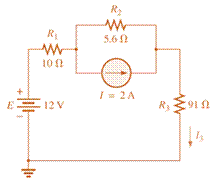
For the configuration of Fig. 8.112:
a. Convert the current source to a voltage source.
b. Combine the two series voltage sources into one source.
c. Calculate the current through the 91

Fig. 8.112
Expert Solution & Answer
Want to see the full answer?
Check out a sample textbook solution
Students have asked these similar questions
Fundamentals of Energy Systems HW 2 Q5
Fundamentals of Energy Systems HW 2 Q7
Fundamentals of Energy Systems HW 2 Q1
Chapter 8 Solutions
Laboratory Manual for Introductory Circuit Analysis
Ch. 8 - For the network of Fig. 8.103: a. Find the...Ch. 8 - For the network of Fig. 8.104: a. Determine the...Ch. 8 - Find voltage Vs (with polarity) across the ideal...Ch. 8 - For the network in Fig. 8.106: a. Find voltage Vs....Ch. 8 - Find the voltage V3 and the current I2 for the...Ch. 8 - For the network in Fig. 8.108: a. Find the...Ch. 8 - Convert the voltage sources in Fig. 8.109 to...Ch. 8 - Convert the current sources in Fig. 8.110 to...Ch. 8 - For the network in Fig. 8.111: Find the current IL...Ch. 8 - For the configuration of Fig. 8.112: a. Convert...
Ch. 8 - For the network in Fig. 8.113: a. Replace all the...Ch. 8 - Find the voltage Vs and the current I1 for the...Ch. 8 - Convert the voltage sources in Fig. 8.115 to...Ch. 8 - For the network in Fig. 8.116, reduce the network...Ch. 8 - Using branch-current analysis, find the magnitude...Ch. 8 - For the network of Fig. 8.118: Determine the...Ch. 8 - Using branch-current analysis, find the current...Ch. 8 - Using branch-current analysis, find the current...Ch. 8 - For the network in Fig. 8.121: a. Write the...Ch. 8 - Using the general approach to mesh analysis,...Ch. 8 - Using the general approach to mesh analysis,...Ch. 8 - Using the general approach to mesh analysis,...Ch. 8 - Using the general approach to mesh analysis,...Ch. 8 - Determine the mesh currents for the network of...Ch. 8 - Write the mesh equations for the network of Fig....Ch. 8 - Write the mesh equations for thesss network of...Ch. 8 - Write the mesh currents for the network of Fig....Ch. 8 - Redraw the network of Fig. 8.125 in a manner that...Ch. 8 - For the transistor configuration in Fig. 8.126: a....Ch. 8 - Using the supermesh approach, find the current...Ch. 8 - Using the supermesh approach, find the current...Ch. 8 - Using the format approach to mesh analysis, write...Ch. 8 - Using the format approach to mesh analysis, write...Ch. 8 - Using the format approach to mesh analysis, write...Ch. 8 - Write the mesh equations for the network of Fig....Ch. 8 - Write the mesh equations for the network of Fig....Ch. 8 - a. Write the mesh equations for the network of...Ch. 8 - Write the mesh equations for the network of Fig....Ch. 8 - Write the mesh equations for the network of Fig....Ch. 8 - a. Write the mesh equations for the network of...Ch. 8 - a. Write the nodal equations using the general...Ch. 8 - Write the nodal equations using the general...Ch. 8 - a. Write the nodal equations using the general...Ch. 8 - a. Write the nodal equations for the network of...Ch. 8 - a. Write the nodal equations for the network of...Ch. 8 - a. Write the nodal equations for the network of...Ch. 8 - Write the nodal equations for the network of Fig....Ch. 8 - Write the nodal equations for the network of Fig....Ch. 8 - Write the nodal equations for the network of Fig....Ch. 8 - Using the supernode approach, determine the nodal...Ch. 8 - Using the supernode approach, determine the nodel...Ch. 8 - Determine the nodal voltages of Fig. 8.130 using...Ch. 8 - Convert the voltage source of Fig 8.131 to a...Ch. 8 - Convert the voltage source of Fig. 8.136 to a...Ch. 8 - Apply the format approach of nodal analysis to the...Ch. 8 - Using the format approach, find the nodal voltages...Ch. 8 - Convert the voltage sources of Fig. 8.129 to...Ch. 8 - For the network of Fig. 8.135: a. Convert the...Ch. 8 - For the bridge network in Fig. 8.141: a. Write the...Ch. 8 - For the network in Fig. 8.141: a. Write the nodal...Ch. 8 - For the bridge in Fig. 8.142: a. Write the mesh...Ch. 8 - For the bridge network in Fig. 8.142: a. Write the...Ch. 8 - Determine the current through the source resistor...Ch. 8 - Repeat Problem 63 for the network of Fig. 8.144....Ch. 8 - Using a -Y or Y- conversion, find the current I...Ch. 8 - Convert the of 6.8 k resistors in Fig. 8.146 to...Ch. 8 - For the network of Fig. 8.147, find the current I...Ch. 8 - a. Using a -Y or Y- conversion, find the current...Ch. 8 - The network of Fig. 8.149 is very similar to the...Ch. 8 - a. Replace the TT configuration in Fig.8.150...Ch. 8 - Using Y or Yconversion, determine the total...Ch. 8 - Using schematics, find the current through each...Ch. 8 - Using schematics, find the mesh currents for the...Ch. 8 - Using schematics, determine the nodal voltages for...
Additional Engineering Textbook Solutions
Find more solutions based on key concepts
Assume a telephone signal travels through a cable at two-thirds the speed of light. How long does it take the s...
Electric Circuits. (11th Edition)
A nozzle at A discharges water with an initial velocity of 36 ft/s at an angle with the horizontal. Determine ...
Vector Mechanics For Engineers
What types of coolant are used in vehicles?
Automotive Technology: Principles, Diagnosis, And Service (6th Edition) (halderman Automotive Series)
The solid steel shaft AC has a diameter of 25 mm and is supported by smooth bearings at D and E. It is coupled ...
Mechanics of Materials (10th Edition)
A byte is made up of eight a. CPUs b. addresses c. variables d. bits
Starting Out with Java: From Control Structures through Objects (7th Edition) (What's New in Computer Science)
In Exercises 1 through 22, determine the output displayed in the text box or list box by the lines of code.
Introduction To Programming Using Visual Basic (11th Edition)
Knowledge Booster
Learn more about
Need a deep-dive on the concept behind this application? Look no further. Learn more about this topic, electrical-engineering and related others by exploring similar questions and additional content below.Similar questions
- Don't use ai to answer I will report you answerarrow_forwardtype (o) bT S+αT Profational controller a = b = 5, T-La |kp| 50 5+50 kp=20,50,70 ② type (1) bT 5(stat) a=b=5,T= 1 ✓ KT 5 SC5+5 kp=20, 50, 70 (Find Wny, ess for type (a) and (1))arrow_forward2. Write an expression of the two sinusoidal voltage waveforms whose effective value is 7.071 V and whose phase difference is 90 degrees. Draw the phasor of those two sinusoidal waveforms in the complex plane.arrow_forward
- 2. Determine developed torque and shaft torque of 220-V, 4-pole series motor with 800 conductors wave-connected supplying a load of 8.2kW by taking 45A from the mains. The flux per pole is 25 mWb and its armature circuit resistance is 0.60. Ans.[143.25 Nm, 135.25 Nm]arrow_forward7. resistance): The practical capacitor can be simplified as the model below (ESR: equivalent series 10 μF ESR W From a datasheet, it is known that a 10 µF aluminum electrolytic capacitor has an impedance of 2800 mOhm at the 100 kHz testing condition. (1) Calculate the ESR under the above testing condition; (2) Calculate the phase shift between the voltage and current at 100 Hz and 10k Hz sinusoidal excitation conditions.arrow_forward5. A circuit has the following AC sources: y₁ = 5 cos(wt + 30°), y₂ = 4 cos(2wt + 120°), y3 = 3 cos(4wt - 60°), y4 = 6 cos(2wt - 120°), y = 2√2cos(wt - 60°): (1) Identify fundamental sources and harmonics. (2) Using phasor approach to simplify y₁ + y2 y3 y4 y5 as much as possible.arrow_forward
- 6. A practical 10 μH wire wounded inductor has a series parasitic resistance of 0.4 Ohm, as shown in the figure below. a 10 pH 0.4 Ω W° b If an AC current y₁ = 4cos (20πt + 60°) is supplied to this inductor, (1) calculate the voltage across the inductor terminals a and b. (2) express the inductor terminal voltage and current in the complex plane. (3) calculate the phase shift between inductor terminal voltage and current If an AC current y₂ = 4cos (2000лt + 60°) is supplied to this inductor, (4) calculate the voltage across the inductor terminals a and b. (5) express the inductor terminal voltage and current in the complex plane. (6) calculate the phase shift between inductor terminal voltage and currentarrow_forward1. As shown below, an LED lightbulb is connected to the grid power. The LED lightbulb has a rated power of 15 W, and the gird voltage is 120 V 60 Hz. Based on the above information (1) what is the peak value and effective value of the current flowing through the LED light bulb, (2) write an expression of the current flowing through the LED light bulb.arrow_forwardQ4: Determine the reactions at support A in structure shown in figure below. 4 kN/m 2.5 kN/m 9 m 4 marrow_forward
arrow_back_ios
SEE MORE QUESTIONS
arrow_forward_ios
Recommended textbooks for you
 Delmar's Standard Textbook Of ElectricityElectrical EngineeringISBN:9781337900348Author:Stephen L. HermanPublisher:Cengage Learning

Delmar's Standard Textbook Of Electricity
Electrical Engineering
ISBN:9781337900348
Author:Stephen L. Herman
Publisher:Cengage Learning
Kirchhoff's Rules of Electrical Circuits; Author: Flipping Physics;https://www.youtube.com/watch?v=d0O-KUKP4nM;License: Standard YouTube License, CC-BY