
Videos
Find the distance a.
Answer to Problem 7.148P
The distance a is
Explanation of Solution
Given information:
The length of the cable AB is
The value of angle
The collar at A is slides freely and the collar at B is prevented from the moving.
Calculation:
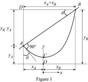
Show the free-body diagram of the cable assembly as in Figure 1.
Refer Equation 7.16 in the textbook.
Write the equation of the catenary cable as follows;
Differentiate the equation with x;
The slope at point A is;
The length of the portion AC is;
The length of the portion CB is;
Find the distance
Substitute 10 ft for L,
Find the distance
Find the distance
Consider the triangle ABD;
Find the value of
Find the distance a using the relation.
Use the trial and error procedure to find the value of a.
Consider the value of c and for the given value of
Find the angle
Trial 1:
Consider a trial value of 1.60 ft for c.
Substitute 1.60 ft for c and
Substitute 1.60 ft for c and 1.410 ft for
Substitute 1.60 ft for c and 1.410 ft for
Substitute 1.60 ft for c and 3.777 ft for
Substitute 1.410 ft for
The calculated value of
Trial 2:
Consider a trial value of 1.70 ft for c.
Substitute 1.70 ft for c and
Substitute 1.70 ft for c and 1.498 ft for
Substitute 1.70 ft for c and 1.498 ft for
Substitute 1.70 ft for c and 3.891 ft for
Substitute 1.498 ft for
The calculated value of
Trial 3:
Consider a trial value of 1.8652 ft for c.
Substitute 1.8652 ft for c and
Substitute 1.8652 ft for c and 1.644 ft for
Substitute 1.8652 ft for c and 1.644 ft for
Substitute 1.8652 ft for c and 4.064 ft for
Substitute 1.644 ft for
The calculated value of
Therefore, the value of c is 1.8652 ft.
Substitute 2.638 ft for
Therefore, the distance a is
Want to see more full solutions like this?
Chapter 7 Solutions
VECTOR MECHANICS FOR ENGINEERS: STATICS


- The average heat transfer coefficent for airflow over an odd shaped body is to be determined by mass transfer measurements and using the Chilton-Colburn analogy btwn heat and mass transfer. The experiemnt is conducted by blowing dry air at 1 atm at a free-stream velocity of 2 m/s over a body covered with a layer of naphthalene. The surface area of the body is .75 m^2, and it is observed that 100 g of maphthalene has sublimated in 45 min. During the experiemnt, both the body and the air were kep at 25oC, at which the vapor pressure and mass diffusivity of naphthalene are 11 Pa and Dab=0.61*10^-5 m^2/s respectively. Determine the heat transfer coefficent under the same flow conditions over the same geometry.arrow_forwardAuto Controls Design a PID controller for thefollowing system so that the modified system satisfies the followingspecifications : 1. settling time ,ts = 1.96 s and % Overshoot Mp = 70.7 % Assume a non-dominant pole at s = -15 to solve the problem The plot the compensated andThen plot the uncompensated system in MATLAB. what can you see from the plot ? what is your observation ?arrow_forwardAuto Controls The figure is a schematic diagram of an aircraft elevator control system. The input to the systemin the deflection angle of the control lever , and the output is the elevator angle phi.show that for each angle theta of the control lever ,there is a corresponding elevator angle phi. Then find Y(s)/theta(s) and simplify the resulting transfer function . Also note from the diagram that y and phi is relatedarrow_forward
- Fresh water is planned to be pumped in a certain pipe at constant pumping rate of 6.5 gpm. If water density and viscosity are 8.34 ppg and 1.0 cp, what is the minimum pipe inside diameter that make the fluid flow behave as turbulent flow?arrow_forwardUSE MATLAB ONLY provide typed code Turbomachienery . GIven: vx = 185 m/s, flow angle = 60 degrees, R = 0.5, U = 150 m/s, b2 = -a3, a2 = -b3 Find: velocity triangle , a. magnitude of abs vel leaving rotor (m/s) b. flow absolute angles (a1, a2, a3) 3. flow rel angles (b2, b3) d. specific work done e. use code to draw vel. diagram Use this code for plot % plots Velocity Tri. in Ch4 function plotveltri(al1,al2,al3,b2,b3) S1L = [0 1]; V1x = [0 0]; V1s = [0 1*tand(al3)]; S2L = [2 3]; V2x = [0 0]; V2s = [0 1*tand(al2)]; W2s = [0 1*tand(b2)]; U2x = [3 3]; U2y = [1*tand(b2) 1*tand(al2)]; S3L = [4 5]; V3x = [0 0]; V3r = [0 1*tand(al3)]; W3r = [0 1*tand(b3)]; U3x = [5 5]; U3y = [1*tand(b3) 1*tand(al3)]; plot(S1L,V1x,'k',S1L,V1s,'r',... S2L,V2x,'k',S2L,V2s,'r',S2L,W2s,'b',U2x,U2y,'g',... S3L,V3x,'k',S3L,V3r,'r',S3L,W3r,'b',U3x,U3y,'g',...... 'LineWidth',2,'MarkerSize',10),... axis([-1 6 -4 4]), ... title('Velocity Triangle'), ... xlabel('x'),ylarrow_forwardConsider a 12 cm internal diameter, 14 m long circular duct whose interior surface is wet. The duct is to be dried by forcing dry air at 1 atm and 15oC throught it at an average velocity of 3m/s. The duct passes through a chilled roo, and it remains at an average temp of 15oC at all time. Determine the mass transfer coeeficient in the duct.arrow_forward
- Consider a 5m by 5m wet concret patio with an average water film thickness of .2mm. Now wind at 50 km/h is blowing over the surface. If the air is at 1 atm, 15oC and 35 percent relative humidity, determine how long it will take for the patio to completely dry.arrow_forwardA double thread worm gear has a pitch of 1 1/8 and a pitch diameter of 3 in. It has a coefficient of friction of 0.20 and normal angle (pressure angle) of 14.5o. The worm is supplied by 12 hp at 1200 rpm motor. Find the tangential force on the gear. The worm is left hand threads.arrow_forwardA double thread worm gear has a pitch of 1 1/8 and a pitch diameter of 3 in. It has a coefficient of friction of 0.20 and normal angle (pressure angle) of 14.5o. The worm is supplied by 12 hp at 1200 rpm motor. Find the tangential force on the gear. The worm is left hand threads.arrow_forward
- A 2 mm thick, 5L vessel made of nickel is used ot store hydrogen gas at 358 K and 300 kPa. If the total inner surface area of the vessel is 1600 cm^2, determine the rate of gas loss from the nickel vessel via mas diffusion. Also, determine the fraction of the hydrogen lost by mass diffusion after one year of storage.arrow_forward< 7:19 The 1st homework 6. Multiple Choice a)唧筒机构 5G31 Which of followings can be th e kinematic diagram of this mechanism? A B Darrow_forward2:54 The 1st homework . 5G 27 b)回转柱塞泵机构 Which of followings can be the kinematic diagram of this mechanis m? A B D Carrow_forward
 Elements Of ElectromagneticsMechanical EngineeringISBN:9780190698614Author:Sadiku, Matthew N. O.Publisher:Oxford University Press
 Mechanics of Materials (10th Edition)Mechanical EngineeringISBN:9780134319650Author:Russell C. HibbelerPublisher:PEARSON
 Thermodynamics: An Engineering ApproachMechanical EngineeringISBN:9781259822674Author:Yunus A. Cengel Dr., Michael A. BolesPublisher:McGraw-Hill Education
 Control Systems EngineeringMechanical EngineeringISBN:9781118170519Author:Norman S. NisePublisher:WILEY
 Mechanics of Materials (MindTap Course List)Mechanical EngineeringISBN:9781337093347Author:Barry J. Goodno, James M. GerePublisher:Cengage Learning
 Engineering Mechanics: StaticsMechanical EngineeringISBN:9781118807330Author:James L. Meriam, L. G. Kraige, J. N. BoltonPublisher:WILEY