
Mechanics of Materials
9th Edition
ISBN: 9780133254426
Author: Russell C. Hibbeler
Publisher: Prentice Hall
expand_more
expand_more
format_list_bulleted
Videos
Textbook Question
Chapter 7.3, Problem 7.6FP
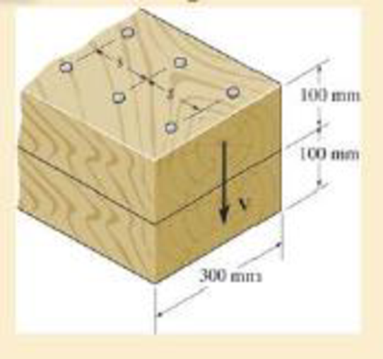
The two identical boards are bolted together to form the beam. Determine the maximum spacing s of the bolts to the nearest mm if each bolt has a shear strength of 15 kN. The beam is subjected to a shear force of V = 50 kN.
F7–6
Expert Solution & Answer

Learn your wayIncludes step-by-step video

schedule04:26
Students have asked these similar questions
A turbine blade made of a metal alloy (k=17 W/m-K) has a length of 5.3 cm, a perimeter of 11 cm, and a cross-sectional
area of 5.13 cm². The turbine blade is exposed to hot gas from the combustion chamber at 1133°C with a convection heat
transfer coefficient of 538 W/m²K. The base of the turbine blade maintains a constant temperature of 450°C and the tip is
adiabatic.
NOTE: This is a multi-part question. Once an answer is submitted, you will be unable to return to this part.
Hot gas
h=538 W/m²K
-Turbine blade
k = 17 W/m-K
p=11 cm, L=5.3 cm
A = 5.13 cm²
-T=450°C
Determine the heat transfer rate to the turbine blade.
W.
The heat transfer rate is
Consider a very long, slender rod. One end of the rod is attached to a base surface maintained at Tb, while the surface of
the rod is exposed to an air temperature of 400°C. Thermocouples imbedded in the rod at locations 25 mm and 120 mm
from the base surface register temperatures of 325°C and 375°C, respectively.
NOTE: This is a multi-part question. Once an answer is submitted, you will be unable to return to this part.
.
x1
32
x
Calculate the rod base temperature (°C).
The rod base temperature is
°C.
Air
T∞
(read image)
Chapter 7 Solutions
Mechanics of Materials
Ch. 7.2 - In each case, calculate the value of Q and t that...Ch. 7.2 - If the beam is subjected to a shear force of V =...Ch. 7.2 - Determine the shear stress at points A and B if...Ch. 7.2 - Determine the absolute maximum shear stress in the...Ch. 7.2 - If the beam is subjected to a shear force of V =20...Ch. 7.2 - If the beam is made from four plates and subjected...Ch. 7.2 - If the wide-flange beam is subjected to a shear of...Ch. 7.2 - If the wide-flange beam is subjected to a shear of...Ch. 7.2 - If the wide-flange beam is subjected to a shear of...Ch. 7.2 - Prob. 7.4P
Ch. 7.2 - Prob. 7.5PCh. 7.2 - The wood beam has an allowable shear stress of...Ch. 7.2 - The shaft is supported by a thrust bearing at A...Ch. 7.2 - The shaft is supported by a thrust bearing at A...Ch. 7.2 - Determine the largest shear force V that the...Ch. 7.2 - If the applied shear force V = 18 kip, determine...Ch. 7.2 - The overhang beam is subjected to the uniform...Ch. 7.2 - *7-12. The beam has a rectangular cross section...Ch. 7.2 - Determine the maximum shear stress in the strut if...Ch. 7.2 - Determine the maximum shear force V that the strut...Ch. 7.2 - 7-15. The strut is subjected to a vertical shear...Ch. 7.2 - Prob. 7.16PCh. 7.2 - If the beam is subjected to a shear of V=15 kN,...Ch. 7.2 - If the wide-flange beam is subjected to a shear of...Ch. 7.2 - If the wide-flange beam is subjected to a shear of...Ch. 7.2 - Prob. 7.20PCh. 7.2 - If the beam is made from wood having an allowable...Ch. 7.2 - Determine the shear stress at point B on the web...Ch. 7.2 - Determine the maximum shear stress acting at...Ch. 7.2 - Prob. 7.24PCh. 7.2 - 7-25. Determine the maximum shear stress in the...Ch. 7.2 - 7-26. The beam has a square cross section and is...Ch. 7.2 - The beam is slit longitudinally along both sides....Ch. 7.2 - The beam is to be cut longitudinally along both...Ch. 7.2 - The beam has a rectangular cross section and is...Ch. 7.2 - The beam in Fig.6-48f is subjected to a fully...Ch. 7.3 - The two identical boards are bolted together to...Ch. 7.3 - Two identical 20-mm-thick plates are bolted to the...Ch. 7.3 - The boards are bolted together to form the...Ch. 7.3 - The boards are bolted together to form the...Ch. 7.3 - Prob. 7.32PCh. 7.3 - Prob. 7.33PCh. 7.3 - Prob. 7.34PCh. 7.3 - Prob. 7.35PCh. 7.3 - Prob. 7.36PCh. 7.3 - Prob. 7.37PCh. 7.3 - Prob. 7.38PCh. 7.3 - A beam is constructed from three boards bolted...Ch. 7.3 - The simply supported beam is built up from three...Ch. 7.3 - The simply supported beam is built up from three...Ch. 7.3 - The T-beam is constructed as shown. If each nail...Ch. 7.3 - Prob. 7.43PCh. 7.3 - Prob. 7.44PCh. 7.3 - Prob. 7.45PCh. 7.3 - 7–46. The beam is subjected to a shear of V = 800...Ch. 7.3 - The beam is made from four boards nailed together...Ch. 7.3 - The beam is made from three polystyrene strips...Ch. 7.5 - A shear force of V=300 kN is applied to the box...Ch. 7.5 - A shear force of V=450 kN is applied to the box...Ch. 7.5 - A shear force of V = 18 kN is applied to the box...Ch. 7.5 - A shear force of V = 18 kN is applied to the box...Ch. 7.5 - The aluminum strut is 10 mm thick and has the...Ch. 7.5 - The aluminum strut is 10 mm thick and has the...Ch. 7.5 - Prob. 7.56PCh. 7.5 - Prob. 7.57PCh. 7.5 - Prob. 7.58PCh. 7.5 - Prob. 7.59PCh. 7.5 - The built-up beam is formed by welding together...Ch. 7.5 - The assembly is subjected to a vertical shear of V...Ch. 7.5 - 7–62. Determine the shear-stress variation over...Ch. 7.5 - 7–63. Determine the location e of the shear...Ch. 7.5 - Determine the location e of the shear center,...Ch. 7.5 - The beam supports a vertical shear of V=7 kip....Ch. 7.5 - The stiffened beam is constructed from plates...Ch. 7.5 - The pipe is subjected to a shear force of V=8 kip....Ch. 7.5 - *7–68. A thin plate of thickness t is bent to form...Ch. 7.5 - A thin plate of thickness t is bent to form the...Ch. 7.5 - 7–70. Determine the location e of the shear...Ch. 7 - The beam is fabricated from four boards nailed...Ch. 7 - The T-beam is subjected to a shear of V = 150 kN....Ch. 7 - The member is subject to a shear force of V = 2...Ch. 7 - Determine the shear stress at points B and C on...Ch. 7 - Determine the maximum shear stress acting at...
Additional Engineering Textbook Solutions
Find more solutions based on key concepts
In the circuit shown in Fig. P 7.26, both switches operate together; that is, they either open or close at the ...
Electric Circuits. (11th Edition)
Determine the magnitude of the resultant force acting on the plate and its direction, measured counter-clockwis...
INTERNATIONAL EDITION---Engineering Mechanics: Statics, 14th edition (SI unit)
13. Consider the following strange, but true, units:
1 batman = 3 kilograms [kg] 1 hogshead = 63 gallons [gal]
...
Thinking Like an Engineer: An Active Learning Approach (4th Edition)
True or False: If a subclass constructor does not explicitly call a superclass constructor, Java will not call ...
Starting Out with Java: From Control Structures through Data Structures (4th Edition) (What's New in Computer Science)
Find the Error 33. The following pseudocode algorithm has an error. It is supposed to use values input for a re...
Starting Out with C++: Early Objects (9th Edition)
T F It is legal to define a pointer to a class object.
Starting Out with C++ from Control Structures to Objects (9th Edition)
Knowledge Booster


Learn more about
Need a deep-dive on the concept behind this application? Look no further. Learn more about this topic, mechanical-engineering and related others by exploring similar questions and additional content below.Similar questions
- This is a tilt and rotation question. Here are notes attached for reference. ONLY UPLOAD A SOLUTION IF YOU ARE SURE ABOUT THE ANSWER PLEASE.arrow_forwardWhat is the difference between true stress/strain and engineering stess/strain? And how do I calculate them?arrow_forwardA rotating shaft of 20 mm diameter is simply supported. The shaft is loaded with a transverse load of 10 kN as shown in the figure. The shaft is made from AISI 1095 hot-rolled steel. The surface has been machined. The shaft operate at temperature T = 450 °C. Consider a reliability factor of 95%. Determine (a) Calculate the reaction forces R, and R₂ (2 points) (b) Draw the shear force and bending moment diagrams and determine the maximum bending moment and shear force. (6 points) 200 mm 20 mm 10,000 N -50 mm- A Not to scale. (c) Determine the critical location of the shaft and the maximum effective stresses. (3 points) (d) Calculate the safety factor against yielding. Does the shaft undergo local yielding? (2 points) (e) Determined the endurance limit, adjusted as necessary with Marin factors. (12 points) (f) Calculate the fatigue factor of safety based on achieving infinite life. (2 points) (g) If the fatigue factor of safety is less than 1 (hint: it should be for this problem), then…arrow_forward
- (read image)arrow_forward(read image)arrow_forward6: Refer to the figure.Given: W1 = 200 kN/m; W2 = 300 kN/m; L1 = 2 m; L2 = 3 m; L3 = 2 m(a) Calculate the total length L so that the resulting upward pressureq is uniform. (b) draw the shear and moment diagram and determinethe maximum shear, maximum positive and negative bendingmoments.arrow_forward
- A six cylinder, four-stroke diesel engine develops a power of 200 kW at 2000 rpm. The bsfc is 0.2 kW/kg h of fuel with 34.9° API. The fuel is injected at an average pressure of 350 bar and the pressure in the combustion chamber is 40 bar. Assuming Ca for injector 0.75 and the atmospheric pressure 1 bar. Determine the period of injection in seconds if the total orifice area required per injector is 0.4876 × 10⁻⁶ m².arrow_forwardTrieed a detailed drawing Win explanatio LL Antsmi 1981x pu + 96252 اه 6. The Pre-combustion chamber design engines employ nozzle type commonly referred to as a ....... a. inward-opening nozzle b. multiple-hole nozzle. c. pintle nozzle. d. none of these. 7. If the temperature of the spark plug tip is less than 350 °C, ......... a. the plug might not work. b. the carbon deposits would increase. 8. Port injection sprays fuel....... c. pre-ignition will occur. d. none of these. a. towards the intake valve. b. in the engine cylinder. c. in the throttle body assembly. d. none of these. 9. When the fuel-air mixture changed from best power to a richer ratio, the spark advance should be........ a. increased. b. decreased. c. left unchanged. d. none of these. d. none of these. 10. Spark plugs are classified as hot plugs and cold plugs depending upon ........ a. spark gap. b. the type of plug c. the operating temperature insulator. range of the electrode tip. ---20125 750 x2.01 SP 5.arrow_forwardA 1. How does the octane number (O.N.) of the fuel a. Higher ignition advance is required for a high O.N. fuel. b. Higher ignition retard is required for a high O.N. fuel. affect spark ing:d. Nou does not affect spark timing. c. The octane number 2. How does the ignition system account for load change? these. of a. The throttle b. The vacuum ignition governor c. The mechanism of d. None of is wide opened. provide additional spark advance at part throttle positions. centrifugal advance does the job. these. 3. In the common rail fuel system the fuel is metered by ........ a. low pressure pump. b. injectors. c. high pressure pump. d. none of these. 4.......... is the time period, measured in degrees of cam rotation, during which the contact points remain closed between each opening. a. Distributor. b. Dwell. c. ECU. d. none of these. 5. The trigger wheel in TCI system replaces the ......... used in a contact breaker distributor. a. pickup coil. b. distributor cam. c. condenser. 750 x2.01…arrow_forward
- a い يكا 4 +91- pu Answer the following statements by true or false, giving the reason for your answer: 1. Injection pressure in CI engines should be sufficiently high. 2. The purpose of the condenser in battery ignition system is to prevent spark in the ignition coil assembly. 3. An idling engine requires lean mixture of fuel and air. 4. Factors which decide optimum engine firing order are engine vibration, engine cooling and back pressure. 5. It is the duty of the header to control over speeding during CI engine operation when drastic reduction in load occurs. ---20125 750 x2.01 SParrow_forward6. The Pre-combustion chamber design engines employ nozzle type commonly referred to as a a. inward-opening nozzle b. multiple-hole nozzle. c. pintle nozzle. d. none of these. 7. If the temperature of the spark plug tip is less than 350 °C, ........ a. the plug might b. the carbon deposits not work. would increase. c. pre-ignition will occur. d. none of these. 8. Port injection sprays fuel........ a. towards the intake valve. b. in the engine cylinder. c. in the throttle body d. none of assembly. these. 9. When the fuel-air mixture changed from best power to a richer ratio, the spark advance should be ........ a. increased. b. decreased. c. left unchanged. d. none of these. 10. Spark plugs are classified as hot plugs and cold plugs depending upon a. spark gap. b. the type of plug c. the operating temperature d. none of these. range of the electrode tip. insulator.arrow_forward1: A H = 6 m cantilever retaining wall is subjected to a soil pressurelinearly varying from zero at the top to 90 kPa at the bottom. As an additionalsupport, it is anchored at depth y = 2 m. with maximum tension equal to 25kN. Assume that the stem provides fully retrained support. Draw the shearand moment diagram of the wall to calculate the following: (a) Maximumpositive bending moment per linear meter; (b) maximum negative bendingmoment per linear meter; (c) maximum shear force per linear meter.arrow_forward
arrow_back_ios
SEE MORE QUESTIONS
arrow_forward_ios
Recommended textbooks for you
 Elements Of ElectromagneticsMechanical EngineeringISBN:9780190698614Author:Sadiku, Matthew N. O.Publisher:Oxford University Press
 Mechanics of Materials (10th Edition)Mechanical EngineeringISBN:9780134319650Author:Russell C. HibbelerPublisher:PEARSON
 Thermodynamics: An Engineering ApproachMechanical EngineeringISBN:9781259822674Author:Yunus A. Cengel Dr., Michael A. BolesPublisher:McGraw-Hill Education
 Control Systems EngineeringMechanical EngineeringISBN:9781118170519Author:Norman S. NisePublisher:WILEY
 Mechanics of Materials (MindTap Course List)Mechanical EngineeringISBN:9781337093347Author:Barry J. Goodno, James M. GerePublisher:Cengage Learning
 Engineering Mechanics: StaticsMechanical EngineeringISBN:9781118807330Author:James L. Meriam, L. G. Kraige, J. N. BoltonPublisher:WILEY
Elements Of Electromagnetics
Mechanical Engineering
ISBN:9780190698614
Author:Sadiku, Matthew N. O.
Publisher:Oxford University Press
Mechanics of Materials (10th Edition)
Mechanical Engineering
ISBN:9780134319650
Author:Russell C. Hibbeler
Publisher:PEARSON
Thermodynamics: An Engineering Approach
Mechanical Engineering
ISBN:9781259822674
Author:Yunus A. Cengel Dr., Michael A. Boles
Publisher:McGraw-Hill Education
Control Systems Engineering
Mechanical Engineering
ISBN:9781118170519
Author:Norman S. Nise
Publisher:WILEY
Mechanics of Materials (MindTap Course List)
Mechanical Engineering
ISBN:9781337093347
Author:Barry J. Goodno, James M. Gere
Publisher:Cengage Learning
Engineering Mechanics: Statics
Mechanical Engineering
ISBN:9781118807330
Author:James L. Meriam, L. G. Kraige, J. N. Bolton
Publisher:WILEY
Mechanics of Materials Lecture: Beam Design; Author: UWMC Engineering;https://www.youtube.com/watch?v=-wVs5pvQPm4;License: Standard Youtube License