
Mechanics of Materials
9th Edition
ISBN: 9780133254426
Author: Russell C. Hibbeler
Publisher: Prentice Hall
expand_more
expand_more
format_list_bulleted
Videos
Textbook Question
Chapter 7.5, Problem 7.50P
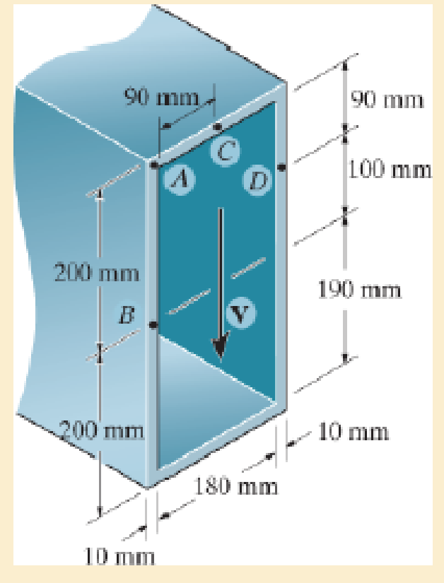
A shear force of V=300 kN is applied to the box girder. Determine the shear flow at points A and B.
Probs. 7–50/51
Expert Solution & Answer
Want to see the full answer?
Check out a sample textbook solution
Students have asked these similar questions
Qu 4 The 12-kg slender rod is attached to a spring, which has an unstretched length of 2 m. If the rod is
released from rest when 0 = 30°, determine its angular velocity at the instant 0 = 90°.
2 m
B
k = 40 N/m
2 m
CORRECT AND DETAILED HANDWRITTEN SOLUTION WITH FBD ONLY. I WILL UPVOTE THANK YOU. CORRECT ANSWER IS ALREADY PROVIDED.
13: A cantilever beam is of length 1.5 m,loaded by a concentrated load P at its tip as shown inFig. 8-18(a), and is of circular cross section (R = 100 mm),having two symmetrically placed longitudinal holes asindicated. The material is titanium alloy, having anallowable working stress in bending of 600 MPa.Determine the maximum allowable value of the verticalforce P. ANS: P = 236,589.076 N = 236.589 kN
CORRECT AND DETAILED HANDWRITTEN SOLUTION WITH FBD ONLY. I WILL UPVOTE THANK YOU. CORRECT ANSWER IS ALREADY PROVIDED.
15: Consider a beam having an I-type cross section as shown in Fig. 8-45. Ashearing force V of 150 kN acts over the section. Determine the maximum and minimumvalues of the shearing stress in the vertical web of the section.ANS: fv(max) = 44.048 MPa ; fv(min) = 33.202 MPa
Chapter 7 Solutions
Mechanics of Materials
Ch. 7.2 - In each case, calculate the value of Q and t that...Ch. 7.2 - If the beam is subjected to a shear force of V =...Ch. 7.2 - Determine the shear stress at points A and B if...Ch. 7.2 - Determine the absolute maximum shear stress in the...Ch. 7.2 - If the beam is subjected to a shear force of V =20...Ch. 7.2 - If the beam is made from four plates and subjected...Ch. 7.2 - If the wide-flange beam is subjected to a shear of...Ch. 7.2 - If the wide-flange beam is subjected to a shear of...Ch. 7.2 - If the wide-flange beam is subjected to a shear of...Ch. 7.2 - Prob. 7.4P
Ch. 7.2 - Prob. 7.5PCh. 7.2 - The wood beam has an allowable shear stress of...Ch. 7.2 - The shaft is supported by a thrust bearing at A...Ch. 7.2 - The shaft is supported by a thrust bearing at A...Ch. 7.2 - Determine the largest shear force V that the...Ch. 7.2 - If the applied shear force V = 18 kip, determine...Ch. 7.2 - The overhang beam is subjected to the uniform...Ch. 7.2 - *7-12. The beam has a rectangular cross section...Ch. 7.2 - Determine the maximum shear stress in the strut if...Ch. 7.2 - Determine the maximum shear force V that the strut...Ch. 7.2 - 7-15. The strut is subjected to a vertical shear...Ch. 7.2 - Prob. 7.16PCh. 7.2 - If the beam is subjected to a shear of V=15 kN,...Ch. 7.2 - If the wide-flange beam is subjected to a shear of...Ch. 7.2 - If the wide-flange beam is subjected to a shear of...Ch. 7.2 - Prob. 7.20PCh. 7.2 - If the beam is made from wood having an allowable...Ch. 7.2 - Determine the shear stress at point B on the web...Ch. 7.2 - Determine the maximum shear stress acting at...Ch. 7.2 - Prob. 7.24PCh. 7.2 - 7-25. Determine the maximum shear stress in the...Ch. 7.2 - 7-26. The beam has a square cross section and is...Ch. 7.2 - The beam is slit longitudinally along both sides....Ch. 7.2 - The beam is to be cut longitudinally along both...Ch. 7.2 - The beam has a rectangular cross section and is...Ch. 7.2 - The beam in Fig.6-48f is subjected to a fully...Ch. 7.3 - The two identical boards are bolted together to...Ch. 7.3 - Two identical 20-mm-thick plates are bolted to the...Ch. 7.3 - The boards are bolted together to form the...Ch. 7.3 - The boards are bolted together to form the...Ch. 7.3 - Prob. 7.32PCh. 7.3 - Prob. 7.33PCh. 7.3 - Prob. 7.34PCh. 7.3 - Prob. 7.35PCh. 7.3 - Prob. 7.36PCh. 7.3 - Prob. 7.37PCh. 7.3 - Prob. 7.38PCh. 7.3 - A beam is constructed from three boards bolted...Ch. 7.3 - The simply supported beam is built up from three...Ch. 7.3 - The simply supported beam is built up from three...Ch. 7.3 - The T-beam is constructed as shown. If each nail...Ch. 7.3 - Prob. 7.43PCh. 7.3 - Prob. 7.44PCh. 7.3 - Prob. 7.45PCh. 7.3 - 7–46. The beam is subjected to a shear of V = 800...Ch. 7.3 - The beam is made from four boards nailed together...Ch. 7.3 - The beam is made from three polystyrene strips...Ch. 7.5 - A shear force of V=300 kN is applied to the box...Ch. 7.5 - A shear force of V=450 kN is applied to the box...Ch. 7.5 - A shear force of V = 18 kN is applied to the box...Ch. 7.5 - A shear force of V = 18 kN is applied to the box...Ch. 7.5 - The aluminum strut is 10 mm thick and has the...Ch. 7.5 - The aluminum strut is 10 mm thick and has the...Ch. 7.5 - Prob. 7.56PCh. 7.5 - Prob. 7.57PCh. 7.5 - Prob. 7.58PCh. 7.5 - Prob. 7.59PCh. 7.5 - The built-up beam is formed by welding together...Ch. 7.5 - The assembly is subjected to a vertical shear of V...Ch. 7.5 - 7–62. Determine the shear-stress variation over...Ch. 7.5 - 7–63. Determine the location e of the shear...Ch. 7.5 - Determine the location e of the shear center,...Ch. 7.5 - The beam supports a vertical shear of V=7 kip....Ch. 7.5 - The stiffened beam is constructed from plates...Ch. 7.5 - The pipe is subjected to a shear force of V=8 kip....Ch. 7.5 - *7–68. A thin plate of thickness t is bent to form...Ch. 7.5 - A thin plate of thickness t is bent to form the...Ch. 7.5 - 7–70. Determine the location e of the shear...Ch. 7 - The beam is fabricated from four boards nailed...Ch. 7 - The T-beam is subjected to a shear of V = 150 kN....Ch. 7 - The member is subject to a shear force of V = 2...Ch. 7 - Determine the shear stress at points B and C on...Ch. 7 - Determine the maximum shear stress acting at...
Knowledge Booster


Learn more about
Need a deep-dive on the concept behind this application? Look no further. Learn more about this topic, mechanical-engineering and related others by exploring similar questions and additional content below.Similar questions
- CORRECT AND DETAILED HANDWRITTEN SOLUTION WITH FBD ONLY. I WILL UPVOTE THANK YOU. CORRECT ANSWER IS ALREADY PROVIDED. 12: A steel cantilever beam 16 ft 8 in in length is subjected to a concentrated load of 320 lb acting at the freeend of the bar. A commercially available rolled steel section, designated as W12x32, is used for the beam. Assume that the total depth of the beam is 12 in, and the neutral axis of the section is in the middle. Determine the maximum tensile and compressive stresses. (Properties of commercially available rolled steel section provided in the table. Z = section modulus). ANS: σT = σC = 1,572.482 lb/in2arrow_forwardCORRECT AND DETAILED HANDWRITTEN SOLUTION WITH FBD ONLY. I WILL UPVOTE THANK YOU. CORRECT ANSWER IS ALREADY PROVIDED. 14: Two ½-in x 8-in cover plates are welded to two channels 10 in high to formthe cross section of the beam shown in Fig. 8-59. Loads are in a vertical plane and bendingtakes place about a horizontal axis. The moment of inertia of each channel about ahorizontal axis through the centroid is 78.5 in4. If the maximum allowable elastic bendingstress is 18,000 lb/in2, determine the maximum bending moment that may be developedin the beam.ANS: 1,236,000 lb-in.arrow_forwardCORRECT AND DETAILED HANDWRITTEN SOLUTION WITH FBD ONLY. I WILL UPVOTE THANK YOU. CORRECT ANSWER IS ALREADY PROVIDED. 11: A beam of circular cross section is 7 in in diameter. It is simply supported at each end and loaded by twoconcentrated loads of 20,000 lb each, applied 12 in from the ends of the beam. Determine the maximum bending stressin the beam. ANS: σ = 7,127.172 lb/in2arrow_forward
- using the theorem of three moments, find all the reactions and supportsarrow_forward(An ellipsoidal trapping region for the Lorenz equations) Show that there is a certain ellipsoidal region E of the form rx2 + σy2 + σ(z − 2r)2 ≤ C such that all trajectories of the Lorenz equations eventually enter E and stay in there forever. For a much stiffer challenge, try to obtain the smallest possible value of C with this property.arrow_forwardA) In a factory, an s-type pitot tube was used to calculate the velocity of dry air for a point inside a stack. Calculate the velocity at that point (ft/sec) using following conditions: ● • • Pressure = 30.23 ± 0.01 in Hg (ambient) Pitot tube coefficient = 0.847 ± 0.03 Temperature = 122 ± 0.1 F (stack) Temperature = 71.2 ± 0.1 F (ambient) AP = 0.324 ± 0.008 in H2O (pitot tube) • AP = 0.891 ± 0.002 in H2O (stack) B) Find the dominant error(s) when determining precision for the problem. C) For part A, what is the precision in ft/sec for the velocity?arrow_forward
- Q1/ For what value of x do the power series converge: 8 (-1)n-1. x2n-1 2n-1 x3 x5 = X n=1 3 Q2/ Find the Interval of convergence and Radius of convergence of the series: 8 n Σ 3+1 n=1 (x)"arrow_forwardExample-1: l D A uniform rotor of length 0.6 m and diameter 0.4 m is made of steel (density 7810 kg/m³) is supported by identical short bearings of stiffness 1 MN/m in the horizontal and vertical directions. If the distance between the bearings is 0.7 m, determine the natural frequencies and plot whirl speed map. Solution: Barrow_forwardfind the laplace transform for the flowing function 2(1-e) Ans. F(s)=- S 12) k 0 Ans. F(s)= k s(1+e) 0 a 2a 3a 4a 13) 2+ Ans. F(s)= 1 s(1+e") 3 14) f(t)=1, 0arrow_forwardFind the solution of the following Differential Equations Using Laplace Transforms 1) 4y+2y=0. y(0)=2. y'(0)=0. 2) y+w²y=0, (0)=A, y'(0)=B. 3) +2y-8y 0. y(0)=1. y'(0)-8. 4)-2-3y=0, y(0)=1. y'(0)=7. 5) y-ky'=0, y(0)=2, y'(0)=k. 6) y+ky'-2k²y=0, y(0)=2, y'(0) = 2k. 7) '+4y=0, y(0)=2.8 8) y+y=17 sin(21), y(0)=-1. 9) y-y-6y=0, y(0)=6, y'(0)=13. 10) y=0. y(0)=4, y' (0)=0. 11) -4y+4y-0, y(0)=2.1. y'(0)=3.9 12) y+2y'+2y=0, y(0)=1, y'(0)=-3. 13) +7y+12y=21e". y(0)=3.5. y'(0)=-10. 14) "+9y=10e". y(0)=0, y'(0)=0. 15) +3y+2.25y=91' +64. y(0)=1. y'(0) = 31.5 16) -6y+5y-29 cos(2t). y(0)=3.2, y'(0)=6.2 17) y+2y+2y=0, y(0)=0. y'(0)=1. 18) y+2y+17y=0, y(0)=0. y'(0)=12. 19) y"-4y+5y=0, y(0)=1, y'(0)=2. 20) 9y-6y+y=0, (0)-3, y'(0)=1. 21) -2y+10y=0, y(0)=3, y'(0)=3. 22) 4y-4y+37y=0, y(0)=3. y'(0)=1.5 23) 4y-8y+5y=0, y(0)=0, y'(0)=1. 24) ++1.25y-0, y(0)=1, y'(0)=-0.5 25) y 2 cos(r). y(0)=2. y'(0) = 0. 26) -4y+3y-0, y(0)=3, y(0) 7. 27) y+2y+y=e y(0)=0. y'(0)=0. 28) y+2y-3y=10sinh(27), y(0)=0. y'(0)=4. 29)…arrow_forwardAuto Controls A union feedback control system has the following open loop transfer function where k>0 is a variable proportional gain i. for K = 1 , derive the exact magnitude and phase expressions of G(jw). ii) for K = 1 , identify the gaincross-over frequency (Wgc) [where IG(jo))| 1] and phase cross-overfrequency [where <G(jw) = - 180]. You can use MATLAB command "margin" to obtain there quantities. iii) Calculate gain margin (in dB) and phase margin (in degrees) ·State whether the closed-loop is stable for K = 1 and briefly justify your answer based on the margin . (Gain marginPhase margin) iv. what happens to the gain margin and Phase margin when you increase the value of K?you You can use for loop in MATLAB to check that.Helpful matlab commands : if, bode, margin, rlocus NO COPIED SOLUTIONSarrow_forwardThe 120 kg wheel has a radius of gyration of 0.7 m. A force P with a magnitude of 50 N is applied at the edge of the wheel as seen in the diagram. The coefficient of static friction is 0.3, and the coefficient of kinetic friction is 0.25. Find the acceleration and angular acceleration of the wheel.arrow_forwardarrow_back_iosSEE MORE QUESTIONSarrow_forward_ios
Recommended textbooks for you
 Elements Of ElectromagneticsMechanical EngineeringISBN:9780190698614Author:Sadiku, Matthew N. O.Publisher:Oxford University Press
 Mechanics of Materials (10th Edition)Mechanical EngineeringISBN:9780134319650Author:Russell C. HibbelerPublisher:PEARSON
 Thermodynamics: An Engineering ApproachMechanical EngineeringISBN:9781259822674Author:Yunus A. Cengel Dr., Michael A. BolesPublisher:McGraw-Hill Education
 Control Systems EngineeringMechanical EngineeringISBN:9781118170519Author:Norman S. NisePublisher:WILEY
 Mechanics of Materials (MindTap Course List)Mechanical EngineeringISBN:9781337093347Author:Barry J. Goodno, James M. GerePublisher:Cengage Learning
 Engineering Mechanics: StaticsMechanical EngineeringISBN:9781118807330Author:James L. Meriam, L. G. Kraige, J. N. BoltonPublisher:WILEY
Elements Of Electromagnetics
Mechanical Engineering
ISBN:9780190698614
Author:Sadiku, Matthew N. O.
Publisher:Oxford University Press
Mechanics of Materials (10th Edition)
Mechanical Engineering
ISBN:9780134319650
Author:Russell C. Hibbeler
Publisher:PEARSON
Thermodynamics: An Engineering Approach
Mechanical Engineering
ISBN:9781259822674
Author:Yunus A. Cengel Dr., Michael A. Boles
Publisher:McGraw-Hill Education
Control Systems Engineering
Mechanical Engineering
ISBN:9781118170519
Author:Norman S. Nise
Publisher:WILEY
Mechanics of Materials (MindTap Course List)
Mechanical Engineering
ISBN:9781337093347
Author:Barry J. Goodno, James M. Gere
Publisher:Cengage Learning
Engineering Mechanics: Statics
Mechanical Engineering
ISBN:9781118807330
Author:James L. Meriam, L. G. Kraige, J. N. Bolton
Publisher:WILEY
Everything About TRANSVERSE SHEAR in 10 Minutes!! - Mechanics of Materials; Author: Less Boring Lectures;https://www.youtube.com/watch?v=4x0E9yvzfCM;License: Standard Youtube License