
EBK ENGINEERING MECHANICS STATICS
15th Edition
ISBN: 9780135187777
Author: HIBBELER
Publisher: PEARSON
expand_more
expand_more
format_list_bulleted
Concept explainers
Videos
Textbook Question
thumb_up100%
Chapter 7.1, Problem 9P
Take P = 8 kN.
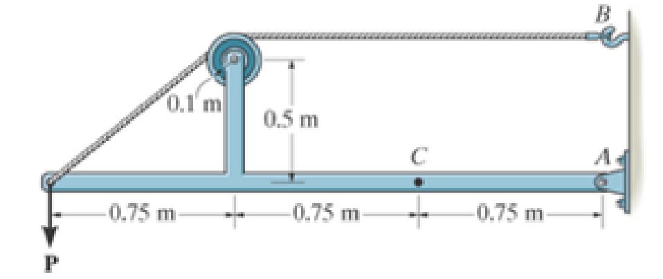
Prob. 7-9
Expert Solution & Answer
Want to see the full answer?
Check out a sample textbook solution
Students have asked these similar questions
A carbon steel ball with 27.00-mm diameter is pressed together with an aluminum ball
with a 36.00-mm diameter by a force of 11.00 N. Determine the maximum shear
stress and the depth at which it will occur for the aluminum ball. Assume the figure
given below, which is based on a typical Poisson's ratio of 0.3, is applicable to estimate
the depth at which the maximum shear stress occurs for these materials.
1.0
0.8
Ratio of stress to Pma
9 0.6
στ
24
0.4
Tmax
0.2
0
0.5a
a
1.5a
Z
2a
2.5a
За
Distance from contact surface
The maximum shear stress is determined to be
MPa.
The depth in the aluminum ball at which the maximum shear stress will occur is
determined to be [
mm.
Show all work please
Draw top, side, front view With pen(cil) and paper
Multi view drawing and handwriting all of it
Chapter 7 Solutions
EBK ENGINEERING MECHANICS STATICS
Ch. 7.1 - In each case, calculate the reaction at A and then...Ch. 7.1 - Determine the normal force, shear force, and...Ch. 7.1 - Determine the normal force, shear force, and...Ch. 7.1 - Determine the normal force, shear force, and...Ch. 7.1 - Determine the normal force, shear force, and...Ch. 7.1 - Determine the normal force, shear force, and...Ch. 7.1 - Assume A is pinned and B is a roller. Prob. F7-6Ch. 7.1 - Determine the shear force and moment at points C...Ch. 7.1 - Assume the support at B is a roller. Point C is...Ch. 7.1 - Determine the internal normal force, shear force,...
Ch. 7.1 - Determine the internal normal force, shear force,...Ch. 7.1 - If a force of 20 lb is applied to the handles,...Ch. 7.1 - Determine the distance a as a fraction of the...Ch. 7.1 - Determine the internal shear force and moment...Ch. 7.1 - Determine the internal shear force and moment...Ch. 7.1 - Take P = 8 kN. Prob. 7-9Ch. 7.1 - Determine the largest vertical load P the frame...Ch. 7.1 - Determine the internal normal force, shear force,...Ch. 7.1 - Determine the distance a between the bearings in...Ch. 7.1 - Point D is located just to the left of the 5-kip...Ch. 7.1 - The shaft is supported by a journal bearing at A...Ch. 7.1 - Determine the internal normal force, shear force,...Ch. 7.1 - Determine the internal normal force, shear force,...Ch. 7.1 - Determine the normal force, shear force, and...Ch. 7.1 - Determine the internal normal force, shear force,...Ch. 7.1 - Prob. 19PCh. 7.1 - Determine the internal normal force, shear force,...Ch. 7.1 - Point E is located just to the left of 800 N...Ch. 7.1 - Point D is located just to the left of the roller...Ch. 7.1 - Determine the internal normal force, shear force,...Ch. 7.1 - Determine the ratio of a/b for which the shear...Ch. 7.1 - Point E is just to the right of the 3-kip load....Ch. 7.1 - Determine the internal normal force, shear force,...Ch. 7.1 - Determine the internal normal force, shear force,...Ch. 7.1 - Point D is located just to the left of the 10-kN...Ch. 7.1 - Determine the normal force, shear force, and...Ch. 7.1 - Determine the normal force, shear force, and...Ch. 7.1 - Determine the internal normal force, shear force,...Ch. 7.1 - Determine the internal normal force, shear force,...Ch. 7.1 - Determine the internal normal force, shear force,...Ch. 7.1 - Determine the internal normal force, shear force,...Ch. 7.1 - If the suspended load has a weight of 2 kN and a...Ch. 7.1 - Determine the internal normal force, shear force,...Ch. 7.1 - Determine the internal normal force, shear force,...Ch. 7.1 - Determine the internal normal force, shear force,...Ch. 7.1 - The distributed loading W = W0 sin , measured per...Ch. 7.1 - Solve Prob. 7-39 for = 120. Probs. 739/40Ch. 7.1 - z components of force and moment at point C in the...Ch. 7.1 - Determine the x, y, z components of force and...Ch. 7.1 - Determine the x, y, z components of internal...Ch. 7.1 - Determine the x, y. z components of internal...Ch. 7.2 - Determine the shear and moment as a function of x,...Ch. 7.2 - Determine the shear and moment as a function of x,...Ch. 7.2 - Determine the shear and moment as a function of x,...Ch. 7.2 - Determine the shear and moment as a function of x,...Ch. 7.2 - Determine the shear and moment as a function of x,...Ch. 7.2 - Determine the shear and moment as a function of x,...Ch. 7.2 - Draw the shear and moment diagrams for the shaft...Ch. 7.2 - Draw the shear and moment diagrams for the beam...Ch. 7.2 - Draw the shear and moment diagrams for the beam...Ch. 7.2 - Draw the shear and moment diagrams for the...Ch. 7.2 - Draw the shear and moment diagrams of the beam (a)...Ch. 7.2 - If L = 9 m, the beam will fail when the maximum...Ch. 7.2 - Draw the shear and moment diagrams for the beam....Ch. 7.2 - Draw the shear and moment diagrams for the beam....Ch. 7.2 - Draw the shear and bending-moment diagrams for the...Ch. 7.2 - The shaft is supported by a smooth thrust bearing...Ch. 7.2 - Draw the shear and moment diagrams for the beam....Ch. 7.2 - Draw the shear and moment diagrams for the beam....Ch. 7.2 - Draw the shear and moment diagrams for the...Ch. 7.2 - Draw the shear and bending-moment diagrams for...Ch. 7.2 - Draw the shear and moment diagrams for the beam....Ch. 7.2 - The shaft is supported by a smooth thrust bearing...Ch. 7.2 - Draw the shear and moment diagrams for the beam....Ch. 7.2 - The beam will fail when the maximum internal...Ch. 7.2 - Draw the shear and moment diagrams for the beam....Ch. 7.2 - Draw the shear and moment diagrams for the beam....Ch. 7.2 - Draw the shear and moment diagrams for the beam....Ch. 7.2 - Draw the shear and moment diagrams for the beam....Ch. 7.2 - Determine the internal normal force, shear force,...Ch. 7.2 - The quarter circular rod lies in the horizontal...Ch. 7.2 - Express the internal shear and moment components...Ch. 7.3 - Draw the shear and moment diagrams for the beam....Ch. 7.3 - Draw the shear and moment diagrams for the beam....Ch. 7.3 - Draw the shear and moment diagrams for the beam....Ch. 7.3 - Draw the shear and moment diagrams for the beam....Ch. 7.3 - Draw the shear and moment diagrams for the beam....Ch. 7.3 - Draw the shear and moment diagrams for the beam....Ch. 7.3 - Draw the shear and moment diagrams for the beam....Ch. 7.3 - Draw the shear and moment diagrams for the beam....Ch. 7.3 - Draw the shear and moment diagrams for the beam....Ch. 7.3 - Draw the shear and moment diagrams for the...Ch. 7.3 - Draw the shear and moment diagrams for the beam....Ch. 7.3 - Draw the shear and moment diagrams for the beam....Ch. 7.3 - Draw the shear and moment diagrams for the beam....Ch. 7.3 - Draw the shear and moment diagrams for the beam....Ch. 7.3 - Draw the shear and moment diagrams for the beam....Ch. 7.3 - Draw the shear and moment diagrams for the shaft....Ch. 7.3 - Draw the shear and moment diagrams for the beam....Ch. 7.3 - The beam consists of three segments pin connected...Ch. 7.3 - Draw the shear and moment diagrams for the beam....Ch. 7.3 - Draw the shear and moment diagrams for the beam....Ch. 7.3 - Draw the shear and moment diagrams for the beam....Ch. 7.3 - Draw the shear and moment diagrams for the beam....Ch. 7.3 - Draw the shear and moment diagrams for the beam....Ch. 7.3 - Draw the shear and moment diagrams for the beam....Ch. 7.3 - Draw the shear and moment diagrams for the beam....Ch. 7.3 - Draw the shear and moment diagrams for the beam....Ch. 7.3 - Draw the shear and moment diagrams for the beam....Ch. 7.3 - Draw the shear and moment diagrams for the beam....Ch. 7.3 - Draw the shear and moment diagrams for the beam....Ch. 7.3 - Draw the shear and moment diagrams for the beam....Ch. 7.4 - The cable supports the three loads shown....Ch. 7.4 - The cable supports the three loads shown....Ch. 7.4 - Determine the tension in each segment of the cable...Ch. 7.4 - The cable supports the loading shown. Determine...Ch. 7.4 - The cable supports the loading shown. Determine...Ch. 7.4 - The cable supports the three loads shown....Ch. 7.4 - The cable supports the three loads shown....Ch. 7.4 - Determine the force P needed to hold the cable in...Ch. 7.4 - Determine the maximum uniform loading w, measured...Ch. 7.4 - The cable is subjected to a uniform loading of w =...Ch. 7.4 - The cable AB is subjected to a uniform loading of...Ch. 7.4 - Prob. 105PCh. 7.4 - If yB = 1.5 ft. determine the largest weight of...Ch. 7.4 - The cable supports a girder which weighs 850...Ch. 7.4 - Prob. 108PCh. 7.4 - If the pipe has a mass per unit length of 1500...Ch. 7.4 - Prob. 110PCh. 7.4 - Determine the maximum tension developed in the...Ch. 7.4 - Prob. 112PCh. 7.4 - The cable is subjected to the parabolic loading w...Ch. 7.4 - The power transmission cable weighs 10 lb/fl. If...Ch. 7.4 - The power transmission cable weighs 10 lb/ft. If h...Ch. 7.4 - The man picks up the 52-ft chain and holds it just...Ch. 7.4 - Prob. 117PCh. 7.4 - Prob. 118PCh. 7.4 - Prob. 119PCh. 7.4 - A telephone line (cable) stretches between two...Ch. 7.4 - Prob. 121PCh. 7.4 - Prob. 122PCh. 7.4 - A cable has a weight of 5 lb/ft. If it can span...Ch. 7.4 - Prob. 124PCh. 7.4 - Determine the internal normal force, shear force,...Ch. 7.4 - Determine the normal force, shear force, and...Ch. 7.4 - Draw the shear and moment diagrams for the beam....Ch. 7.4 - Draw the shear and moment diagrams for the beam....Ch. 7.4 - Draw the shear and moment diagrams for the beam....Ch. 7.4 - Prob. 6RP
Additional Engineering Textbook Solutions
Find more solutions based on key concepts
Convert each of the following binary representations to its equivalent base ten form: a. 101010 b. 100001 c. 10...
Computer Science: An Overview (13th Edition) (What's New in Computer Science)
CONCEPT QUESTIONS
15.CQ3 The ball rolls without slipping on the fixed surface as shown. What is the direction ...
Vector Mechanics for Engineers: Statics and Dynamics
How are relationships between tables expressed in a relational database?
Modern Database Management
How is the hydrodynamic entry length defined for flow in a pipe? Is the entry length longer in laminar or turbu...
Fluid Mechanics: Fundamentals and Applications
The job of the _____ is to fetch instructions, carry out the operations commanded by the instructions, and prod...
Starting Out With Visual Basic (8th Edition)
The solid steel shaft AC has a diameter of 25 mm and is supported by smooth bearings at D and E. It is coupled ...
Mechanics of Materials (10th Edition)
Knowledge Booster


Learn more about
Need a deep-dive on the concept behind this application? Look no further. Learn more about this topic, mechanical-engineering and related others by exploring similar questions and additional content below.Similar questions
- A wheel of diameter 150.0 mm and width 37.00 mm carrying a load 2.200 kN rolls on a flat rail. Take the wheel material as steel and the rail material as cast iron. Assume the figure given, which is based on a Poisson's ratio of 0.3, is applicable to estimate the depth at which the maximum shear stress occurs for these materials. At this critical depth, calculate the Hertzian stresses σr, σy, σz, and Tmax for the wheel. 1.0 0.8 0, т Ratio of stress to Pmax 0.4 0.6 90 69 0.2 0.5b b 1.5b Tmax 2b Distance from contact surface The Hertizian stresses are as follows: 02 = or = -23.8 psi for the wheel =| necessary.) σy for the wheel =| MPa σz for the wheel = MPa V4 for the wheel = | MPa 2.5b ཡི 3b MPa (Include a minus sign ifarrow_forwardOnly question 3arrow_forwardOnly question 2arrow_forward
- Solve for the support reactions at A and B. C 3 kN/m B -1.5 m- -1.5 m 1.5 m- 1.5 m-arrow_forward4. Solve for the support reactions at A and B. W1 600 lb/ft W2 150 lb/ft A Barrow_forwardIn cold isostatic pressing, the mold is most typically made of which one of the following: thermosetting polymer tool steel sheet metal textile rubberarrow_forward
- The coefficient of friction between the part and the tool in cold working tends to be: lower higher no different relative to its value in hot workingarrow_forwardThe force F={25i−45j+15k}F={25i−45j+15k} lblb acts at the end A of the pipe assembly shown in (Figure 1). Determine the magnitude of the component F1 which acts along the member AB. Determine the magnitude of the component F2 which acts perpendicular to the AB.arrow_forwardHi can you please help me with the attached question?arrow_forward
arrow_back_ios
SEE MORE QUESTIONS
arrow_forward_ios
Recommended textbooks for you
 International Edition---engineering Mechanics: St...Mechanical EngineeringISBN:9781305501607Author:Andrew Pytel And Jaan KiusalaasPublisher:CENGAGE L
International Edition---engineering Mechanics: St...
Mechanical Engineering
ISBN:9781305501607
Author:Andrew Pytel And Jaan Kiusalaas
Publisher:CENGAGE L
moment of inertia; Author: NCERT OFFICIAL;https://www.youtube.com/watch?v=A4KhJYrt4-s;License: Standard YouTube License, CC-BY