
Videos
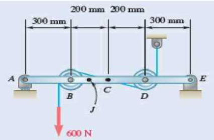
Fig. P7.15 and P7.16
7.16 Knowing that the radius of each pulley is 100 mm and neglecting friction, determine the internal forces at (a) point C, (b) point J that is 100 mm to the left of C.
(a)
The internal forces exerted at the point
Answer to Problem 7.16P
The internal forces of shearing force is
Explanation of Solution
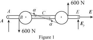
Sketch the free body diagram for the internal forces acting on the frame and pulley system as shown in the Figure 1.
Write the equation of the axial force exerted at the axial point
Here, the force exerted on the frame at the point
Write the equation of the moment of couple formed in the bending moment of the frame and pulley system supported at the point
Here, the axial force exerted on the pulley at point
Write the equation of the axial force exerted at the axial point of the frame from y direction (Refer fig 1).
Here, the axial force exerted on the pulley at point
Sketch the free body diagram for the cable as shown in the Figure 2.
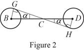
The slope of the cable (Refer fig 2):
The angle formed in the slope of the cable:
Write the equation of the axial force exerted at the axial point
Here, the angle between the pulley
Sketch the free body diagram for the cable for the point
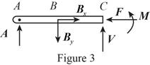
Write the equation of the axial force exerted at the point
Here, shearing force acting on the semicircular rod is
At the pulley
Write the equation of the moment of couple formed in the bending moment supported at the point
Here, the moment of couple exerted at the point
Conclusion:
Substitute
Solve the above equation for
Substitute
Substitute
Substitute
Substitute
The above equation can be written as,
Therefore, The internal forces of shearing force is
(b)
The internal forces exerted at the point
Answer to Problem 7.16P
The internal forces of shearing force is
Explanation of Solution
Sketch the free body diagram for the cable for the point
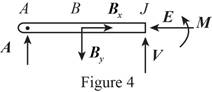
Write the equation of the axial force exerted at the axial point
Here, the force exerted on the frame at the point
Write the equation of the axial force exerted at the axial point of the frame from y direction (Refer fig 4).
Here, the axial force exerted on the pulley at point
Write the equation of the moment of couple formed in the bending moment supported at the point
Here, the moment of couple exerted at the point
Conclusion:
Substitute
Substitute
Substitute
The above equation can be written as,
Therefore, the internal forces of shearing force is
Want to see more full solutions like this?
Chapter 7 Solutions
Vector Mechanics for Engineers: Statics


- My ID# 016948724 please find the forces for Fx=0: fy=0: fz=0: please help me to solve this problem step by steparrow_forwardMy ID# 016948724 please solve the proble step by step find the forces fx=o: fy=0; fz=0; and find shear moment and the bending moment diagran please draw the diagram for the shear and bending momentarrow_forwardMy ID#016948724. Please help me to find the moment of inertia lx ly are a please show to solve step by stepsarrow_forward
- My ID# 016948724arrow_forwardPlease do not use any AI tools to solve this question. I need a fully manual, step-by-step solution with clear explanations, as if it were done by a human tutor. No AI-generated responses, please.arrow_forwardPlease do not use any AI tools to solve this question. I need a fully manual, step-by-step solution with clear explanations, as if it were done by a human tutor. No AI-generated responses, please.arrow_forward
- Please do not use any AI tools to solve this question. I need a fully manual, step-by-step solution with clear explanations, as if it were done by a human tutor. No AI-generated responses, please.arrow_forward[Q2]: The cost information supplied by the cost accountant is as follows:Sales 20,00 units, $ 10 per unitCalculate the (a/ newsale guantity and (b) new selling price to earn the sameVariable cost $ 6 per unit, Fixed Cost $ 30,000, Profit $ 50,000profit ifi) Variable cost increases by $ 2 per unitil) Fixed cost increase by $ 10,000Ili) Variable cost increase by $ 1 per unit and fixed cost reduces by $ 10,000arrow_forwardcan you please help me perform Visual Inspection and Fractography of the attatched image: Preliminary examination to identify the fracture origin, suspected fatigue striation, and corrosion evidences.arrow_forward
 International Edition---engineering Mechanics: St...Mechanical EngineeringISBN:9781305501607Author:Andrew Pytel And Jaan KiusalaasPublisher:CENGAGE L
 Principles of Heat Transfer (Activate Learning wi...Mechanical EngineeringISBN:9781305387102Author:Kreith, Frank; Manglik, Raj M.Publisher:Cengage Learning