
Concept explainers
Videos
For the beam shown, draw the shear and bending-moment diagrams, and determine the magnitude and location of the maximum absolute value of the bending moment, knowing that (a) M = 0, (b) M = 24 kip-ft.
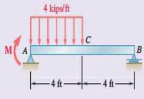
Fig. P7.161
(a)
Plot the shear force and bending moment diagram for the beam.
Find the magnitude and location of the maximum absolute value of the bending moment.
Answer to Problem 7.161RP
The location and magnitude of the maximum absolute bending moment is
Explanation of Solution
Given information:
The moment applied at A is
Calculation:
Show the free-body diagram of the entire beam as in Figure 1.
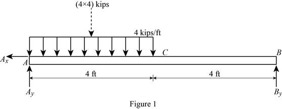
Find the vertical reaction at point B by taking moment about point A.
Find the vertical reaction at point A by reoslving the vertical component of forces.
Resolve the horizontal component of forces.
Consider the section AC:
Consider a section at a distance x from left end A.
Show the free-body diagram of the section as in Figure 2.
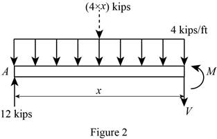
Resolve the vertical component of forces.
Take moment about the section.
At
Substitute 0 for x in Equation (1).
Substitute 0 for x in Equation (2).
At
Substitute 4 ft for x in Equation (1).
Substitute 4 ft for x in Equation (2).
Consider the section CB:
Show the free-body diagram of the section as in Figure 3.
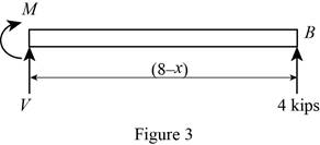
Resolve the vertical component of forces.
Take moment about the section.
At
Substitute 4 ft for x in Equation (3).
At
Substitute 8 ft for x in Equation (3).
Tabulate the shear force values as in Table 1.
| Location, x ft | Shear force, kips |
| 0 | 12 |
| 4 | –4 |
| 8 | –4 |
Plot the shear force diagram as in Figure 4.
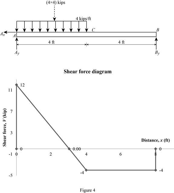
The maximum bending moment occurs where the shear force changes sign.
Refer to the Figure 4, the shear force changes in the section AC.
Substitute 0 for V in Equation (1).
Substitute 3 ft for x in Equaiton (2).
Tabulate the bending moment values as in Table 2.
| Location, x ft | Bending moment, kips-ft |
| 0 | 0 |
| 3 | 18 |
| 4 | 16 |
| 8 | 0 |
Plot the bending moment values as in Figure 5.
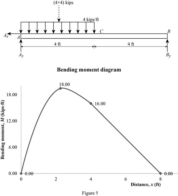
Therefore, the location and magnitude of the maximum absolute bending moment is
(b)
Plot the shear force and bending moment diagram for the beam.
Find the magnitude and location of the maximum absolute value of the bending moment.
Answer to Problem 7.161RP
The location and magnitude of the maximum absolute bending moment is
Explanation of Solution
Given information:
The moment applied at A is
Calculation:
Show the free-body diagram of the entire beam as in Figure 6.
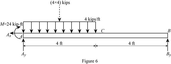
Find the vertical reaction at point B by taking moment about point A.
Find the vertical reaction at point A by reoslving the vertical component of forces.
Resolve the horizontal component of forces.
Consider the section AC:
Consider a section at a distance x from left end A.
Show the free-body diagram of the section as in Figure 7.
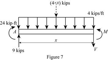
Resolve the vertical component of forces.
Take moment about the section.
At
Substitute 0 for x in Equation (4).
Substitute 0 for x in Equation (5).
At
Substitute 4 ft for x in Equation (4).
Substitute 4 ft for x in Equation (5).
Consider the section CB:
Show the free-body diagram of the section as in Figure 8.
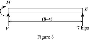
Resolve the vertical component of forces.
Take moment about the section.
At
Substitute 4 ft for x in Equation (6).
At
Substitute 8 ft for x in Equation (6).
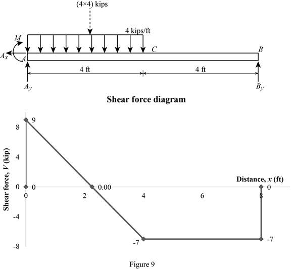
Tabulate the shear force values as in Table 3.
| Location, x ft | Shear force, kips |
| 0 | 9 |
| 4 | –7 |
| 8 | –7 |
Plot the shear force diagram as in Figure 9.
The maximum bending moment occurs where the shear force changes sign.
Refer to the Figure 4, the shear force changes in the section AC.
Substitute 0 for V in Equation (4).
Substitute 2.25 ft for x in Equaiton (5).
Tabulate the bending moment values as in Table 4.
| Location, x ft | Bending moment, kips-ft |
| 0 | 0 |
| 2.25 | 34.125 |
| 4 | 28 |
| 8 | 0 |
Plot the bending moment values as in Figure 10.
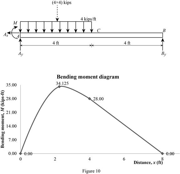
Therefore, the location and magnitude of the maximum absolute bending moment is
Want to see more full solutions like this?
Chapter 7 Solutions
Vector Mechanics for Engineers: Statics


- Please solve this problem as soon as possible My ID# 016948724arrow_forwardThe gears shown in the figure have a diametral pitch of 2 teeth per inch and a 20° pressure angle. The pinion rotates at 1800 rev/min clockwise and transmits 200 hp through the idler pair to gear 5 on shaft c. What forces do gears 3 and 4 transmit to the idler shaft? TS I y 18T 32T This a 12 x 18T C 48T 5arrow_forwardQuestion 1. Draw 3 teeth for the following pinion and gear respectively. The teeth should be drawn near the pressure line so that the teeth from the pinion should mesh those of the gear. Drawing scale (1:1). Either a precise hand drawing or CAD drawing is acceptable. Draw all the trajectories of the involute lines and the circles. Specification: 18tooth pinion and 30tooth gear. Diameter pitch=P=6 teeth /inch. Pressure angle:20°, 1/P for addendum (a) and 1.25/P for dedendum (b). For fillet, c=b-a.arrow_forward
- 5. The figure shows a gear train. There is no friction at the bearings except for the gear tooth forces. The material of the milled gears is steel having a Brinell hardness of 170. The input shaft speed (n2) is 800 rpm. The face width and the contact angle for all gears are 1 in and 20° respectively. In this gear set, the endurance limit (Se) is 15 kpsi and nd (design factor) is 2. (a) Find the revolution speed of gear 5. (b) Determine whether each gear satisfies the design factor of 2.0 for bending fatigue. (c) Determine whether each gear satisfies the design factor of 2.0 for surface fatigue (contact stress). (d) According to the computation results of the questions (b) and (c), explain the possible failure mechanisms for each gear. N4=28 800rpm N₁=43 N5=34 N₂=14 P(diameteral pitch)=8 for all gears Coupled to 2.5hp motorarrow_forward1. The rotating steel shaft is simply supported by bearings at points of B and C, and is driven by a spur gear at D, which has a 6-in pitch diameter. The force F from the drive gear acts at a pressure angle of 20°. The shaft transmits a torque to point A of TA =3000 lbĘ in. The shaft is machined from steel with Sy=60kpsi and Sut=80 kpsi. (1) Draw a shear force diagram and a bending moment diagram by F. According to your analysis, where is the point of interest to evaluate the safety factor among A, B, C, and D? Describe the reason. (Hint: To find F, the torque Tд is generated by the tangential force of F (i.e. Ftangential-Fcos20°) When n=2.5, K=1.8, and K₁ =1.3, determine the diameter of the shaft based on (2) static analysis using DE theory (note that fatigue stress concentration factors need to be used for this question because the loading condition is fatigue) and (3) a fatigue analysis using modified Goodman. Note) A standard diameter is not required for the questions. 10 in Darrow_forward3 N2=28 P(diametral pitch)=8 for all gears Coupled to 25 hp motor N3=34 Full depth spur gears with pressure angle=20° N₂=2000 rpm (1) Compute the circular pitch, the center-to-center distance, and base circle radii. (2) Draw the free body diagram of gear 3 and show all the forces and the torque. (3) In mounting gears, the center-to-center distance was reduced by 0.1 inch. Calculate the new values of center-to-center distance, pressure angle, base circle radii, and pitch circle diameters. (4)What is the new tangential and radial forces for gear 3? (5) Under the new center to center distance, is the contact ratio (mc) increasing or decreasing?arrow_forward
- 2. A flat belt drive consists of two 4-ft diameter cast-iron pulleys spaced 16 ft apart. A power of 60 hp is transmitted by a pulley whose speed is 380 rev/min. Use a service factor (Ks) pf 1.1 and a design factor 1.0. The width of the polyamide A-3 belt is 6 in. Use CD=1. Answer the following questions. (1) What is the total length of the belt according to the given geometry? (2) Find the centrifugal force (Fc) applied to the belt. (3) What is the transmitted torque through the pulley system given 60hp? (4) Using the allowable tension, find the force (F₁) on the tight side. What is the tension at the loose side (F2) and the initial tension (F.)? (5) Using the forces, estimate the developed friction coefficient (f) (6) Based on the forces and the given rotational speed, rate the pulley set. In other words, what is the horse power that can be transmitted by the pulley system? (7) To reduce the applied tension on the tight side, the friction coefficient is increased to 0.75. Find out the…arrow_forwardThe tooth numbers for the gear train illustrated are N₂ = 24, N3 = 18, №4 = 30, №6 = 36, and N₁ = 54. Gear 7 is fixed. If shaft b is turned through 5 revolutions, how many turns will shaft a make? a 5 [6] barrow_forwardCE-112 please solve this problem step by step and give me the correct answerarrow_forward
- CE-112 please solve this problem step by step and give me the correct answerarrow_forwardCE-112 solve this problem step by step and give me the correct answer pleasearrow_forwardPlease do not use any AI tools to solve this question. I need a fully manual, step-by-step solution with clear explanations, as if it were done by a human tutor. No AI-generated responses, please.arrow_forward
 International Edition---engineering Mechanics: St...Mechanical EngineeringISBN:9781305501607Author:Andrew Pytel And Jaan KiusalaasPublisher:CENGAGE L
 Principles of Heat Transfer (Activate Learning wi...Mechanical EngineeringISBN:9781305387102Author:Kreith, Frank; Manglik, Raj M.Publisher:Cengage Learning
 Mechanics of Materials (MindTap Course List)Mechanical EngineeringISBN:9781337093347Author:Barry J. Goodno, James M. GerePublisher:Cengage Learning