
INTERNATIONAL EDITION---Engineering Mechanics: Statics, 14th edition (SI unit)
14th Edition
ISBN: 9780133918922
Author: Russell C. Hibbeler
Publisher: PEARSON
expand_more
expand_more
format_list_bulleted
Videos
Textbook Question
Chapter 7.1, Problem 1PP
In each case, calculate the reaction at A and then draw the free-body diagram of segment AB of the beam in order to determine the internal loading at B.
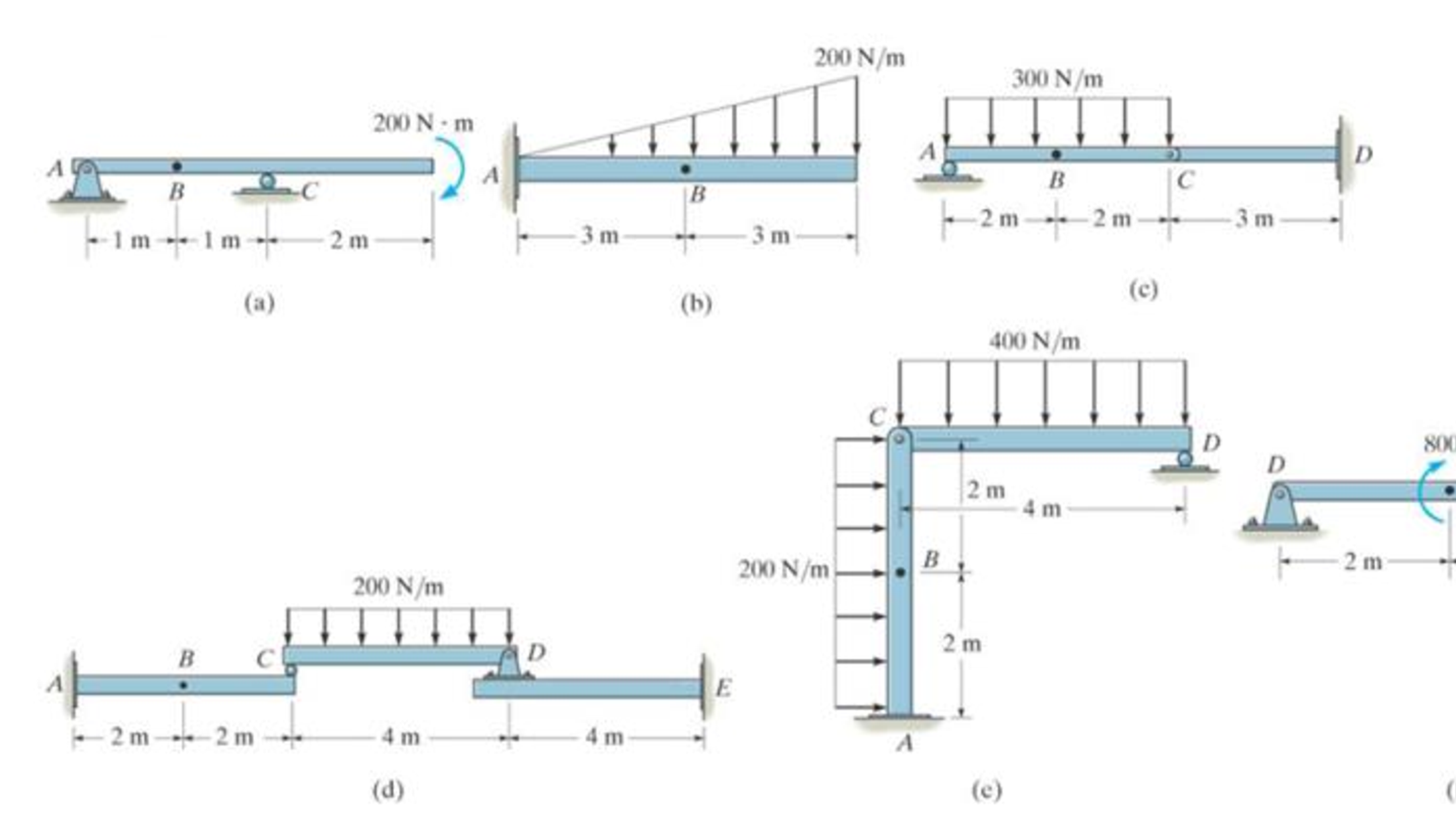
Prob. P7-1
Expert Solution & Answer

Learn your wayIncludes step-by-step video

schedule16:45
Students have asked these similar questions
||!
Sign in
MMB241 - Tutorial L9.pd X PDF MMB241 - Tutorial L10.pX DE MMB241 - Tutorial L11.p x PDF Lecture W12 - Work and X
File C:/Users/KHULEKANI/Desktop/mmb241/MMB241%20-%20Tutorial%20L11.pdf
PDE Lecture W11 - Power and X
Draw
Alla | Ask Copilot
++
3
of 3
| D
6. If the 50-kg load A is hoisted by motor M so that the load has a constant velocity of 1.5
m/s, determine the power input to the motor, which operates at an efficiency € = 0.8.
1.5 m/s
2
7. The sports car has a mass of 2.3 Mg, and while it is traveling at 28 m/s the driver causes
it to accelerate at 5m/s². If the drag resistance on the car due to the wind is FD= 0.3v²N,
where v is the velocity in m/s, determine the power supplied to the engine at this instant.
The engine has a running efficiency of P = 0.68.
8. If the jet on the dragster supplies a constant thrust of T-20 kN, determine the power
generated by the jet as a function of time. Neglect drag and rolling resistance, and the loss
of fuel. The dragster has a mass of 1…
Q |
Sign in
PDE Lecture W09.pdf
PDF MMB241 - Tutorial L9.pdi X
PDF MMB241 - Tutorial L10.p X
PDF
MMB241 - Tutorial L11.p X
Lecture W12-Work and X
+
File C:/Users/KHULEKANI/Desktop/mmb241/Lecture%20W12%20-%20Work%20and%20Energy.pdf
||!
Draw
| IA | a | Ask Copilot
Class Work
+
33
of 34 D
Question 1
The engine of a 3500-N car is generating a constant power of 50 hp (horsepower)
while the car is traveling up the slope with a constant speed. If the engine is
operating with an efficiency of € 0.8, determine the speed of the car. Neglect
drag and rolling resistance. Use g 9.81 m/s² and 1 hp = 745.7 W.
10
го
Question 2
A man pushes on a 60-N crate with a force F. The force is always directed downward at an angle of 30°
from the horizontal, as shown in the figure. The magnitude of the force is gradually increased until the crate
begins to slide. Determine the crate's initial acceleration once it starts to move. Assume the coefficient of
static friction is μ = 0.6, the coefficient of kinetic…
state is
Derive an expression for the volume expansivity of a substance whose equation of
RT
P
=
v-b
a
v(v + b)TZ
where a and b are empirical constants.
Chapter 7 Solutions
INTERNATIONAL EDITION---Engineering Mechanics: Statics, 14th edition (SI unit)
Ch. 7.1 - In each case, calculate the reaction at A and then...Ch. 7.1 - Determine the normal force, shear force, and...Ch. 7.1 - Determine the normal force, shear force, and...Ch. 7.1 - Determine the normal force, shear force, and...Ch. 7.1 - Determine the normal force, shear force, and...Ch. 7.1 - Determine the normal force, shear force, and...Ch. 7.1 - Assume A is pinned and B is a roller. Prob. F7-6Ch. 7.1 - Determine the shear force and moment at points C...Ch. 7.1 - Assume the support at B is a roller. Point C is...Ch. 7.1 - Determine the internal normal force, shear force,...
Ch. 7.1 - Determine the internal normal force, shear force,...Ch. 7.1 - If a force of 20 lb is applied to the handles,...Ch. 7.1 - Determine the distance a as a fraction of the...Ch. 7.1 - Determine the internal shear force and moment...Ch. 7.1 - Determine the internal shear force and moment...Ch. 7.1 - Take P = 8 kN. Prob. 7-9Ch. 7.1 - Determine the largest vertical load P the frame...Ch. 7.1 - Determine the internal normal force, shear force,...Ch. 7.1 - Determine the distance a between the bearings in...Ch. 7.1 - Point D is located just to the left of the 5-kip...Ch. 7.1 - The shaft is supported by a journal bearing at A...Ch. 7.1 - Determine the internal normal force, shear force,...Ch. 7.1 - Determine the internal normal force, shear force,...Ch. 7.1 - Determine the normal force, shear force, and...Ch. 7.1 - Determine the internal normal force, shear force,...Ch. 7.1 - Prob. 19PCh. 7.1 - Determine the internal normal force, shear force,...Ch. 7.1 - Point E is located just to the left of 800 N...Ch. 7.1 - Point D is located just to the left of the roller...Ch. 7.1 - Determine the internal normal force, shear force,...Ch. 7.1 - Determine the ratio of a/b for which the shear...Ch. 7.1 - Point E is just to the right of the 3-kip load....Ch. 7.1 - Determine the internal normal force, shear force,...Ch. 7.1 - Determine the internal normal force, shear force,...Ch. 7.1 - Point D is located just to the left of the 10-kN...Ch. 7.1 - Determine the normal force, shear force, and...Ch. 7.1 - Determine the normal force, shear force, and...Ch. 7.1 - Determine the internal normal force, shear force,...Ch. 7.1 - Determine the internal normal force, shear force,...Ch. 7.1 - Determine the internal normal force, shear force,...Ch. 7.1 - Determine the internal normal force, shear force,...Ch. 7.1 - If the suspended load has a weight of 2 kN and a...Ch. 7.1 - Determine the internal normal force, shear force,...Ch. 7.1 - Determine the internal normal force, shear force,...Ch. 7.1 - Determine the internal normal force, shear force,...Ch. 7.1 - The distributed loading W = W0 sin , measured per...Ch. 7.1 - Solve Prob. 7-39 for = 120. Probs. 739/40Ch. 7.1 - z components of force and moment at point C in the...Ch. 7.1 - Determine the x, y, z components of force and...Ch. 7.1 - Determine the x, y, z components of internal...Ch. 7.1 - Determine the x, y. z components of internal...Ch. 7.2 - Determine the shear and moment as a function of x,...Ch. 7.2 - Determine the shear and moment as a function of x,...Ch. 7.2 - Determine the shear and moment as a function of x,...Ch. 7.2 - Determine the shear and moment as a function of x,...Ch. 7.2 - Determine the shear and moment as a function of x,...Ch. 7.2 - Determine the shear and moment as a function of x,...Ch. 7.2 - Draw the shear and moment diagrams for the shaft...Ch. 7.2 - Draw the shear and moment diagrams for the beam...Ch. 7.2 - Draw the shear and moment diagrams for the beam...Ch. 7.2 - Draw the shear and moment diagrams for the...Ch. 7.2 - Draw the shear and moment diagrams of the beam (a)...Ch. 7.2 - If L = 9 m, the beam will fail when the maximum...Ch. 7.2 - Draw the shear and moment diagrams for the beam....Ch. 7.2 - Draw the shear and moment diagrams for the beam....Ch. 7.2 - Draw the shear and bending-moment diagrams for the...Ch. 7.2 - The shaft is supported by a smooth thrust bearing...Ch. 7.2 - Draw the shear and moment diagrams for the beam....Ch. 7.2 - Draw the shear and moment diagrams for the beam....Ch. 7.2 - Draw the shear and moment diagrams for the...Ch. 7.2 - Draw the shear and bending-moment diagrams for...Ch. 7.2 - Draw the shear and moment diagrams for the beam....Ch. 7.2 - The shaft is supported by a smooth thrust bearing...Ch. 7.2 - Draw the shear and moment diagrams for the beam....Ch. 7.2 - The beam will fail when the maximum internal...Ch. 7.2 - Draw the shear and moment diagrams for the beam....Ch. 7.2 - Draw the shear and moment diagrams for the beam....Ch. 7.2 - Draw the shear and moment diagrams for the beam....Ch. 7.2 - Draw the shear and moment diagrams for the beam....Ch. 7.2 - Determine the internal normal force, shear force,...Ch. 7.2 - The quarter circular rod lies in the horizontal...Ch. 7.2 - Express the internal shear and moment components...Ch. 7.3 - Draw the shear and moment diagrams for the beam....Ch. 7.3 - Draw the shear and moment diagrams for the beam....Ch. 7.3 - Draw the shear and moment diagrams for the beam....Ch. 7.3 - Draw the shear and moment diagrams for the beam....Ch. 7.3 - Draw the shear and moment diagrams for the beam....Ch. 7.3 - Draw the shear and moment diagrams for the beam....Ch. 7.3 - Draw the shear and moment diagrams for the beam....Ch. 7.3 - Draw the shear and moment diagrams for the beam....Ch. 7.3 - Draw the shear and moment diagrams for the beam....Ch. 7.3 - Draw the shear and moment diagrams for the...Ch. 7.3 - Draw the shear and moment diagrams for the beam....Ch. 7.3 - Draw the shear and moment diagrams for the beam....Ch. 7.3 - Draw the shear and moment diagrams for the beam....Ch. 7.3 - Draw the shear and moment diagrams for the beam....Ch. 7.3 - Draw the shear and moment diagrams for the beam....Ch. 7.3 - Draw the shear and moment diagrams for the shaft....Ch. 7.3 - Draw the shear and moment diagrams for the beam....Ch. 7.3 - The beam consists of three segments pin connected...Ch. 7.3 - Draw the shear and moment diagrams for the beam....Ch. 7.3 - Draw the shear and moment diagrams for the beam....Ch. 7.3 - Draw the shear and moment diagrams for the beam....Ch. 7.3 - Draw the shear and moment diagrams for the beam....Ch. 7.3 - Draw the shear and moment diagrams for the beam....Ch. 7.3 - Draw the shear and moment diagrams for the beam....Ch. 7.3 - Draw the shear and moment diagrams for the beam....Ch. 7.3 - Draw the shear and moment diagrams for the beam....Ch. 7.3 - Draw the shear and moment diagrams for the beam....Ch. 7.3 - Draw the shear and moment diagrams for the beam....Ch. 7.3 - Draw the shear and moment diagrams for the beam....Ch. 7.3 - Draw the shear and moment diagrams for the beam....Ch. 7.4 - The cable supports the three loads shown....Ch. 7.4 - The cable supports the three loads shown....Ch. 7.4 - Determine the tension in each segment of the cable...Ch. 7.4 - The cable supports the loading shown. Determine...Ch. 7.4 - The cable supports the loading shown. Determine...Ch. 7.4 - The cable supports the three loads shown....Ch. 7.4 - The cable supports the three loads shown....Ch. 7.4 - Determine the force P needed to hold the cable in...Ch. 7.4 - Determine the maximum uniform loading w, measured...Ch. 7.4 - The cable is subjected to a uniform loading of w =...Ch. 7.4 - The cable AB is subjected to a uniform loading of...Ch. 7.4 - Prob. 105PCh. 7.4 - If yB = 1.5 ft. determine the largest weight of...Ch. 7.4 - The cable supports a girder which weighs 850...Ch. 7.4 - Prob. 108PCh. 7.4 - If the pipe has a mass per unit length of 1500...Ch. 7.4 - Prob. 110PCh. 7.4 - Determine the maximum tension developed in the...Ch. 7.4 - Prob. 112PCh. 7.4 - The cable is subjected to the parabolic loading w...Ch. 7.4 - The power transmission cable weighs 10 lb/fl. If...Ch. 7.4 - The power transmission cable weighs 10 lb/ft. If h...Ch. 7.4 - The man picks up the 52-ft chain and holds it just...Ch. 7.4 - Prob. 117PCh. 7.4 - Prob. 118PCh. 7.4 - Prob. 119PCh. 7.4 - A telephone line (cable) stretches between two...Ch. 7.4 - Prob. 121PCh. 7.4 - Prob. 122PCh. 7.4 - A cable has a weight of 5 lb/ft. If it can span...Ch. 7.4 - Prob. 124PCh. 7.4 - Determine the internal normal force, shear force,...Ch. 7.4 - Determine the normal force, shear force, and...Ch. 7.4 - Draw the shear and moment diagrams for the beam....Ch. 7.4 - Draw the shear and moment diagrams for the beam....Ch. 7.4 - Draw the shear and moment diagrams for the beam....Ch. 7.4 - Prob. 6RP
Additional Engineering Textbook Solutions
Find more solutions based on key concepts
In the circuit shown in Fig. P 7.26, both switches operate together; that is, they either open or close at the ...
Electric Circuits. (11th Edition)
Words that have predefined meaning in a programming language are called _____ .
Starting Out With Visual Basic (8th Edition)
An overridden base class function may be called by a function in a derived class by using the_____________ oper...
Starting Out with C++: Early Objects (9th Edition)
The solid steel shaft AC has a diameter of 25 mm and is supported by smooth bearings at D and E. It is coupled ...
Mechanics of Materials (10th Edition)
File Filter A file filter reads an input file, transforms it in some way, and writes the results to an output F...
Starting Out with C++ from Control Structures to Objects (9th Edition)
The Python built-in function str () will convert a numerical argument into a character string representation, a...
Computer Science: An Overview (13th Edition) (What's New in Computer Science)
Knowledge Booster


Learn more about
Need a deep-dive on the concept behind this application? Look no further. Learn more about this topic, mechanical-engineering and related others by exploring similar questions and additional content below.Similar questions
- For a gas whose equation of state is P(v-b)=RT, the specified heat difference Cp-Cv is equal to which of the following (show all work): (a) R (b) R-b (c) R+b (d) 0 (e) R(1+v/b)arrow_forwardof state is Derive an expression for the specific heat difference of a substance whose equation RT P = v-b a v(v + b)TZ where a and b are empirical constants.arrow_forwardTemperature may alternatively be defined as T = ди v Prove that this definition reduces the net entropy change of two constant-volume systems filled with simple compressible substances to zero as the two systems approach thermal equilibrium.arrow_forward
- Using the Maxwell relations, determine a relation for equation of state is (P-a/v²) (v−b) = RT. Os for a gas whose av Tarrow_forward(◉ Homework#8arrow_forwardHomework#8arrow_forwardBox A has a mass of 15 kilograms and is attached to the 20 kilogram Box B using the cord and pulley system shown. The coefficient of kinetic friction between the boxes and surface is 0.2 and the moment of inertia of the pulley is 0.5 kg * m^ 2. After 2 seconds, how far do the boxes move? A бро Barrow_forwardBox A has a mass of 15 kilograms and is attached to the 20 kilogram Box B using the cord and pulley system shown. The coefficient of kinetic friction between the boxes and surface is 0.2 and the moment of inertia of the pulley is 0.5 kg * m^2. Both boxes are 0.25 m long and 0.25 m high. The cord is attached to the bottom of Box A and the middle of box B. After 2 seconds, how far do the boxes move? A From бро Barrow_forwardHomework#8arrow_forwardSign in PDF Lecture W09.pdf PDF MMB241 - Tutorial L9.pdf File C:/Users/KHULEKANI/Desktop/mmb241/MMB241%20-%20Tutorial%20L9.pdf II! Draw | I│Alla | Ask Copilot + of 4 D Topic: Kinetics of Particles: - Forces in dynamic system, Free body diagram, newton's laws of motion, and equations of motion. TQ1. The 10-kg block is subjected to the forces shown. In each case, determine its velocity when t=2s if v 0 when t=0 500 N F = (201) N 300 N (b) TQ2. The 10-kg block is subjected to the forces shown. In each case, determine its velocity at s-8 m if v = 3 m/s at s=0. Motion occurs to the right. 40 N F = (2.5 s) N 200 N 30 N (b) TQ3. Determine the initial acceleration of the 10-kg smooth collar. The spring has an unstretched length of 1 m. 1 σ Q ☆ Q 6 ا الى ☑arrow_forwardSign in PDF Lecture W09.pdf PDF MMB241 - Tutorial L9.pdf File C:/Users/KHULEKANI/Desktop/mmb241/MMB241%20-%20Tutorial%20L9.pdf II! Draw | I│Alla | Ask Copilot + 4 of 4 | D TQ9. If motor M exerts a force of F (10t 2 + 100) N determine the velocity of the 25-kg crate when t kinetic friction between the crate and the plane are μs The crate is initially at rest. on the cable, where t is in seconds, 4s. The coefficients of static and 0.3 and μk = 0.25, respectively. M 3 TQ10. The spring has a stiffness k = 200 N/m and is unstretched when the 25-kg block is at A. Determine the acceleration of the block when s = 0.4 m. The contact surface between the block and the plane is smooth. 0.3 m F= 100 N F= 100 N k = 200 N/m σ Q Q ☆ ا الى 6 ☑arrow_forwardmy ID# is 016948724 please solve this problem step by steparrow_forwardarrow_back_iosSEE MORE QUESTIONSarrow_forward_iosRecommended textbooks for you
 Elements Of ElectromagneticsMechanical EngineeringISBN:9780190698614Author:Sadiku, Matthew N. O.Publisher:Oxford University Press
 Mechanics of Materials (10th Edition)Mechanical EngineeringISBN:9780134319650Author:Russell C. HibbelerPublisher:PEARSON
 Thermodynamics: An Engineering ApproachMechanical EngineeringISBN:9781259822674Author:Yunus A. Cengel Dr., Michael A. BolesPublisher:McGraw-Hill Education
 Control Systems EngineeringMechanical EngineeringISBN:9781118170519Author:Norman S. NisePublisher:WILEY
 Mechanics of Materials (MindTap Course List)Mechanical EngineeringISBN:9781337093347Author:Barry J. Goodno, James M. GerePublisher:Cengage Learning
 Engineering Mechanics: StaticsMechanical EngineeringISBN:9781118807330Author:James L. Meriam, L. G. Kraige, J. N. BoltonPublisher:WILEY
Elements Of ElectromagneticsMechanical EngineeringISBN:9780190698614Author:Sadiku, Matthew N. O.Publisher:Oxford University PressMechanics of Materials (10th Edition)Mechanical EngineeringISBN:9780134319650Author:Russell C. HibbelerPublisher:PEARSONThermodynamics: An Engineering ApproachMechanical EngineeringISBN:9781259822674Author:Yunus A. Cengel Dr., Michael A. BolesPublisher:McGraw-Hill EducationControl Systems EngineeringMechanical EngineeringISBN:9781118170519Author:Norman S. NisePublisher:WILEYMechanics of Materials (MindTap Course List)Mechanical EngineeringISBN:9781337093347Author:Barry J. Goodno, James M. GerePublisher:Cengage LearningEngineering Mechanics: StaticsMechanical EngineeringISBN:9781118807330Author:James L. Meriam, L. G. Kraige, J. N. BoltonPublisher:WILEY
Mechanics of Materials Lecture: Beam Design; Author: UWMC Engineering;https://www.youtube.com/watch?v=-wVs5pvQPm4;License: Standard Youtube License