
Videos
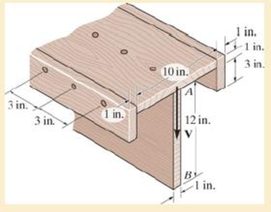
The beam is fabricated from four boards nailed together as shown. Determine the shear force each nail along the sides C and the top D must resist if the nails are uniformly spaced at s=3 in. The beam is subjected to a shear of V=4.5 kip.
The shear force
The shear force
Answer to Problem 7.71RP
The shear force
The shear force
Explanation of Solution
Given information:
The shear force is
The uniform nail spacing is 3 in.
Calculation:
Sketch the diagram of the T section as shown in Figure 1.
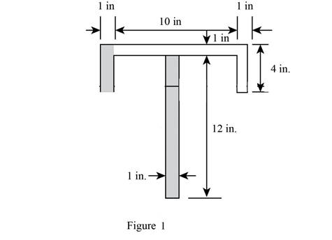
Refer Figure 1,
The area of the beam is the sum of area of three rectangles 1, 2, and 3.
The dimensions of rectangle 1 as width
The dimensions of rectangle 2 as width
The dimensions of rectangle 2 as width
Find the value of area section 1 as shown below:
Substitute 10 in. for
Find the value of area section 2 as shown below:
Substitute 4 in. for
Find the value of area section 3 as shown below:
Substitute 12 in. for
Calculate the centroid of
Here,
Substitute
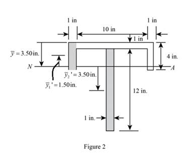
Sketch the diagram of
Calculate the moment of inertia of the beam (I) as follows:
Refer to Figure 2:
The value of
The value of
The value of
Substitute 10 in. for
Calculate the first moment area
Here,
Refer to Figure 2.
The value of
Substitute
Calculate the first moment area
Here,
Refer to Figure 2.
The value of
Substitute
Show the formula for shear flow
Here, V is the shear force, I is the moment of inertia, and
Substitute
Show the formula for shear flow
Here, V is the shear force, I is the moment of inertia, and
Substitute
Calculate the shear force
Here, s is the spacing and
Substitute
Hence, the shear force
Calculate the shear force
Here, s is the spacing and
Substitute
Hence, the shear force
Want to see more full solutions like this?
Chapter 7 Solutions
Mechanics of Materials


- 2: The given continuous beam supports a uniform load with magnitude w. It has an internal hinge at C. (a)Calculate the maximum uniform load w that the beam can carry if it has a moment capacity of 65 kN-m for negativebending; (b) Calculate the maximum uniform load w that the beam can carry if it has a moment capacity of 85 kN-m forpositive bending; (c) Calculate the maximum uniform load w that the beam can carry if it has a shear capacity of 40 kN.arrow_forwardCORRECT AND DETAILED SOLUTION WITH COMPLETE FBD ONLY. I WILL UPVOTE. 10: A wooden beam 150 mm wide by 300 mm deep is loaded asshown. The maximum flexural stress developed is 8 MN/m2. (a) Computethe maximum moment the beam section can resist. (b) Determine themaximum value of the uniform load w in kN/m. (c) Calculate the maximumvalue of the concentrated load P.arrow_forwardThis is a tilt and rotation question. Here are notes attached for reference. ONLY UPLOAD A SOLUTION IF YOU ARE SURE ABOUT THE ANSWER PLEASE.arrow_forward
- (b): Let us first consider controlling the orbit of deputy spacecraft to rendezvous with chief spacecraft. Define x = [r] and x = x = R to represent the deputy orbital state and its target (= chief orbit) in Cartesian coordinates, respectively. The control input is thruster acceleration, u € R³, in the ECI frame. Denote the relative state by dx = x-x. Table 2 summarize the initial orbital elements. Table 2: Keplerian orbital elements at epoch (t = 0) for deputy and chief about Earth (ECI frame) Orbital element Deputy Unit Chief semi-major axis ad = 11500 ac 10000 km eccentricity inclination ed = 0.15 id=35 ee = 0.3 i = 50 degree right ascension of ascending node d = 50 Ως = 50 degree argument of periapsis true anomaly at epoch Wd Vd= 0 = 40 We = 40 degree Ve=0 degree (b.1): Derive the error dynamics of our system in ECI frame under the influence of u. (b.2): Consider a candidate Lyapunov function V = ½dr¹ K₁dr+dv₁dv, where K₁ = K, and K, > 0. Discuss the positive definiteness of V, and…arrow_forwardOne image show problem c.1 and c.2 that I need help with. The second image shows the lyapunov function and its derivative but it is NOT the same function that is given in problem. I have attached that image as an example.arrow_forwardThis is a tilt and rotation question. Here are notes attached for reference.arrow_forward
- The crate of mass m is supported on a cart of negligible mass as shown in (Figure 1). Determine the maximum force P that can be applied a distance d from the cart bottom without causing the crate to tip on the cart. Express your answer in terms of some, all, or none of the variables b, d, h, m, and the acceleration due to gravity g. P B harrow_forwardConsider a pair of pipes running in parallel, through which 1200 GPM flows, which have thefollowing features:Pipe 1: Carbon Steel, Schedule 40, 8" Diameter, 1200 GPM, Water at 44°F, Fittings:2 tees, 2 butterfly valves, 2 pressure gauges with their respective ball valves, 1 valvemotorized balloon. All valves are completely open. Length of the pipe is 6 feet. Pipe 2: consists of a carbon steel bypass pipe, schedule 40, diameter of 4",with the following accessories: 2 elbows long radius of 90° and an open globe valve.The length of the pipe is 10 feet. a) Determine the flow rate in each pipe.b) The pressure drop.arrow_forward1-ft3 of air is contained in a spring-loaded piston-cylinder device. The spring constant is 6 lbf/in, and thepiston diameter is 12 in. When no force is exerted by the spring on the piston, the state of the air is 250 psiaand 450◦F. This device is now cooled until the volume is one-third its original size. Determine the changein the specific internal energy and enthalpy of the air.arrow_forward
- This is a tilt and rotation question. Here are notes attached for reference.arrow_forwardThis is a tilt and rotation question. Here are notes attached for reference.arrow_forwardI need help with a MATLAB code. For question b.6 I have the MATLAB code shown below. How do I edit the code to answer question b.7. Please make sure the plots are reasonable. clc; clear all; % Constants mu = 398600; % Earth gravitational parameter, km^3/s^2 % Initial chief and deputy positions and velocities in ECI frame % Assume circular orbits in equatorial plane for simplicity a_c = 10000; % km a_d = 11500; % km r_c0 = [a_c; 0; 0]; v_c0 = [0; sqrt(mu/a_c); 0]; r_d0 = [a_d; 0; 0]; v_d0 = [0; sqrt(mu/a_d); 0]; % Initial relative state delta_r0 = r_d0 - r_c0; delta_v0 = v_d0 - v_c0; x0 = [delta_r0; delta_v0]; % 6x1 initial relative state % Time span tspan = [0 3600]; % 1 hour in seconds % Damping cases cases = struct( ... 'name', {'Critically damped', 'Under-damped', 'Over-damped'}, ... 'Kr', {eye(3)*2.5e-3, eye(3)*0.001, eye(3)*0.01}, ... 'P', {eye(3)*0.01, eye(3)*0.0006, eye(3)*0.02} ... ); % Simulate each case for i = 1:length(cases) Kr = cases(i).Kr; P =…arrow_forward
 Elements Of ElectromagneticsMechanical EngineeringISBN:9780190698614Author:Sadiku, Matthew N. O.Publisher:Oxford University Press
 Mechanics of Materials (10th Edition)Mechanical EngineeringISBN:9780134319650Author:Russell C. HibbelerPublisher:PEARSON
 Thermodynamics: An Engineering ApproachMechanical EngineeringISBN:9781259822674Author:Yunus A. Cengel Dr., Michael A. BolesPublisher:McGraw-Hill Education
 Control Systems EngineeringMechanical EngineeringISBN:9781118170519Author:Norman S. NisePublisher:WILEY
 Mechanics of Materials (MindTap Course List)Mechanical EngineeringISBN:9781337093347Author:Barry J. Goodno, James M. GerePublisher:Cengage Learning
 Engineering Mechanics: StaticsMechanical EngineeringISBN:9781118807330Author:James L. Meriam, L. G. Kraige, J. N. BoltonPublisher:WILEY