
(a)
Interpretation:
The value of bending stress for given condition should be calculated.
Concept introduction:
Stress is defined as the ratio of load per unit area. It is denoted by
Where,
P is the force in newton.
A is area in square meter.
Bending Stress:
Bending Stress is the amount of stress applied at a point of the body subjected to load results in bending. The formula for bending stress is shown below:
Where,
F is the load in newton.
S is the support span.
t is the thickness in mm.
w is the width in mm.
Standard Deviation:
Standard deviation is the value which defines the variation with respect to mean.
Calculation of value of n using the formula of standard deviation,
Where,
MeanMean is defined as the ratio of the sum of total components with respect to the number of components. The formula for mean is given by,
In mathematical terms the above equation is defined as,
The term
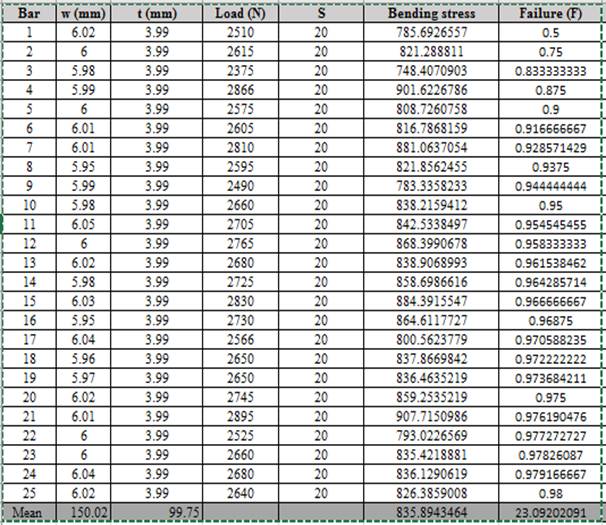
Answer to Problem 7.24P
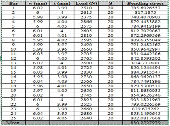
The values of bending stress corresponding to load, thickness and width is shown below,
The requiredvalue of Standard Deviation is
Explanation of Solution
Given information:
The formula for calculation:
Where,
F is the load in newton.
S is the support span.
t is the thickness in mm.
w is the width in mm.
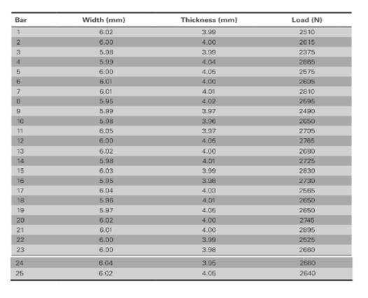
The values of load correspond to length and thickness is shown in table,

The value of supporting span (S) is
Based on given information,
Calculation of bending stress using spreadsheet using the formula of column,
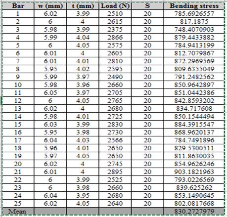
Thus, the bending stress for the given condition of load is shown above.
Calculation of standard deviation using spreadsheet,
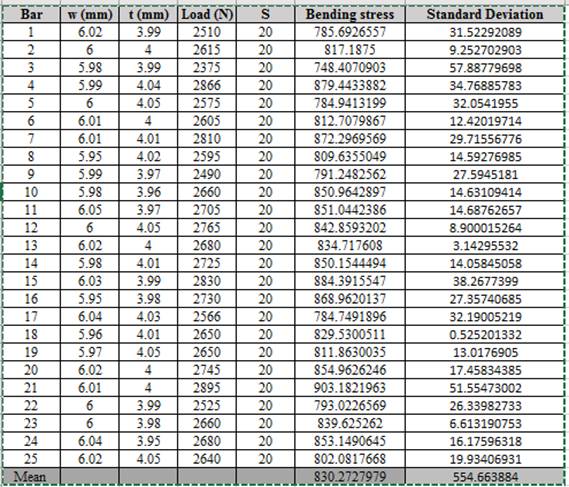
Thus, the required value of standard deviation is
(b)
Interpretation:
Weibull plot using the given condition should be determined. Also, the value of Weibull modulus should be calculated.
Concept introduction:
Weibull plot is used to define the relationship between the fracture of probability with characteristic length.
The relationship is given below:
Where,
F is the failure of probability.
The relation gives Failure of Probability,
Where,
N is the number of variable ranging from 1 to 25.
n is the value of specified strength ranging from lowest strength (1) to highest strength (25).
Answer to Problem 7.24P
Thus, the required Weibull plot is shown below:

Thus, the required value of Weibull modulus is
Explanation of Solution
Given information:
The formula for calculation:
Where,
F is the failure of probability.
The relation gives Failure of Probability,
Where,
N is the number of variable ranging from 1 to 25.
n is the value of specified strength ranging from lowest strength (1) to highest strength (25).
The values of load correspond to length and thickness is shown in table,
The value of lowest strength (n) is 1.
The value of highest strength (n) is 25.
Based on given information,
Calculation of fracture probability using spreadsheet and the relationship used is given below,
Calculation of characteristics length using the data of probability of failure.
Formula used is given below:
Where,
F is the failure of probability.
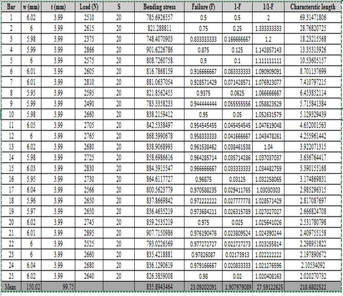
Based on the calculated values of characteristics length and probability of failure, the graph using linear regression is shown below:
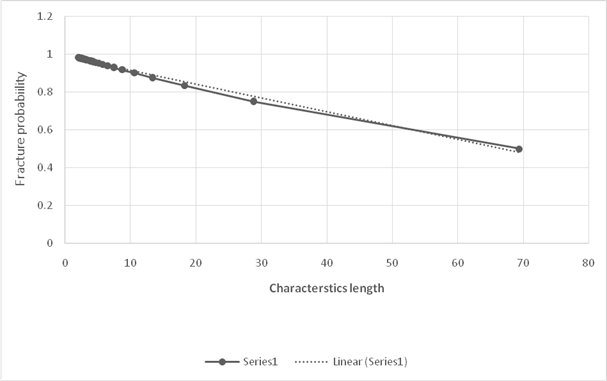
Calculation of Weibull modulus,
Using the equation of straight line considering two points,
Where,
Substituting the values in the above formula,
Thus, the required value of Weibull modulus is
Want to see more full solutions like this?
Chapter 7 Solutions
Essentials Of Materials Science And Engineering

- (read image)arrow_forward(◉ Home - my.uah.edu Homework#5 MasteringEngineering Mastering X + 8 https://session.engineering-mastering.pearson.com/myct/itemView?assignmentProblemID=18992148&offset=nextarrow_forward① Esterfication + R'on R Hydrolysis OH Alcohol A. 0-R Carboxylic Acid Ester NOD-10arrow_forward(◉ Home - my.uah.edu Homework#5 MasteringEngineering Mastering X + 8 https://session.engineering-mastering.pearson.com/myct/itemView?assignmentProblemID=18992144&offset=nextarrow_forwardA4.3- Design a square short column for P₁ = 1800 kN, Mfx = 250 kN.m, Mfy: f your final design p has to be between 0.01 and 0.02. = 50 kN.m. In Given: f'c = 25 MPa fy = 400 MPa Longitudinal bars: Use 25M Ties: 10M@ 300 Clear cover to the ties: 40mmarrow_forwardCalculate the forces in members BC, BG & FG of the truss shown using the Method of Sections. For your answer, provide atruss diagram of the calculated member forces and indicate whether the member is in Tension (+) or Compression (-)arrow_forwardA4.1- For a concentrically loaded tied short column, with the cross-section shown in Figure 1, a) Find the axial load resistance of the column; b) Check if the spacing between the longitudinal bars is satisfying code requirements; c) Determine the required spacing between the ties, and sketch the tie arrangement as per the code. Given: f'c = 25 MPa fy = 400 MPa T 550 mm 550 mm Maximum aggregate size: 20mm Longitudinal bars: 8-25M Figure 1 Ties: 10M (ties are not shown on cross-section. The arrangement to be determined in part c) Clear cover to the ties: 40mmarrow_forward4. a. Determine VDs for VGS = 0 V and ID = 6 mA using the characteristics of Fig. 6.11. b. Using the results of part (a), calculate the resistance of the JFET for the region ID = 0 to 6 mA for VGS = 0 V. c. Determine VDs for VGS = -1 V and ID = 3 mA. d. Using the results of part (c), calculate the resistance of the JFET for the region ID = 0 to 3 mA for VGS = -1 V. e. Determine VDs for VGS = -2 V and ID = 1.5 mA. f. Using the results of part (e), calculate the resistance of the JFET for the region ID = 0 to 1.5 mA for VGS = -2 V. g. Defining the result of part (b) as ro, determine the resistance for VGS = -1 V using Eq. (6.1) and compare with the results of part (d). h. Repeat part (g) for VGS = -2 V using the same equation, and compare the results with part (f). i. Based on the results of parts (g) and (h), does Eq. (6.1) appear to be a valid approximation?arrow_forwardA. Using D flip-flops, design a logic circuit for the finite-state machine described by the state assigned table in Fig. 1. Present Next State State Output x=0 x=1 Y2Y1 Y2Y1 YY Z 00 00 01 0 01 10 11 888 00 10 0 00 10 1 00 10 1 Fig. 1arrow_forwardList all inaccurate or unsupported factual claimsarrow_forwardWhen using a work breakdown structure (WBS) for a project why it is necessary to break down activities?arrow_forwardSelect the speed, feed and depth of the cut to turn wrought, low carbon steel (hardness of 200 BHN) on lathe with AISI tool material of HSS M2 or M3. (Hint: refer to Chapter 21 for recommended parameters).arrow_forwardarrow_back_iosSEE MORE QUESTIONSarrow_forward_iosRecommended textbooks for you
 MATLAB: An Introduction with ApplicationsEngineeringISBN:9781119256830Author:Amos GilatPublisher:John Wiley & Sons Inc
 Essentials Of Materials Science And EngineeringEngineeringISBN:9781337385497Author:WRIGHT, Wendelin J.Publisher:Cengage,
 Industrial Motor ControlEngineeringISBN:9781133691808Author:Stephen HermanPublisher:Cengage Learning
 Basics Of Engineering EconomyEngineeringISBN:9780073376356Author:Leland Blank, Anthony TarquinPublisher:MCGRAW-HILL HIGHER EDUCATION
 Structural Steel Design (6th Edition)EngineeringISBN:9780134589657Author:Jack C. McCormac, Stephen F. CsernakPublisher:PEARSON
 Fundamentals of Materials Science and Engineering...EngineeringISBN:9781119175483Author:William D. Callister Jr., David G. RethwischPublisher:WILEY
MATLAB: An Introduction with ApplicationsEngineeringISBN:9781119256830Author:Amos GilatPublisher:John Wiley & Sons IncEssentials Of Materials Science And EngineeringEngineeringISBN:9781337385497Author:WRIGHT, Wendelin J.Publisher:Cengage,Industrial Motor ControlEngineeringISBN:9781133691808Author:Stephen HermanPublisher:Cengage LearningBasics Of Engineering EconomyEngineeringISBN:9780073376356Author:Leland Blank, Anthony TarquinPublisher:MCGRAW-HILL HIGHER EDUCATIONStructural Steel Design (6th Edition)EngineeringISBN:9780134589657Author:Jack C. McCormac, Stephen F. CsernakPublisher:PEARSONFundamentals of Materials Science and Engineering...EngineeringISBN:9781119175483Author:William D. Callister Jr., David G. RethwischPublisher:WILEY