
Calculate the current response
Answer to Problem 57P
The current response
Explanation of Solution
Given data:
Refer to Figure 7.123 in the textbook.
The value of inductance
The value of inductance
Formula used:
Write the general expression to find the current response for the RL circuit.
Here,
Write the expression to calculate the time constant for the RL circuit.
Here,
L is the inductance of the inductor.
Write the general expression for the unit step function.
Calculation:
For
The given Figure 7.123 is redrawn as shown in Figure 1. At this condition, the inductor reaches steady state and acts like a short circuit to DC.

In Figure 1, apply Kirchhoff’s current law at node
Simplify the equation as follows,
Now find the initial inductor current
Substitute
Now find the initial inductor current
Substitute
For
Figure 2 shows the modified circuit diagram when the switch is kept in closed position.
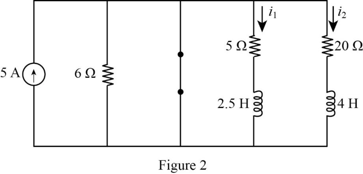
Consider the value of resistances
In Figure 2, the switch is closed so that the energies in the inductance
The current response
The time constant in equation (6) can be rewritten as like in equation (2) as follows.
Substitute
Substitute the units
Substitute
Apply the unit step function in equation (3) to equation (9).
The current response
The time constant in equation (10) can be rewritten as like in equation (2) as follows.
Substitute
Substitute the units
Substitute
Apply the unit step function in equation (3) to equation (13).
Convert the unit A to mA.
Conclusion:
Thus, the current response
Want to see more full solutions like this?
Chapter 7 Solutions
EE 98: Fundamentals of Electrical Circuits - With Connect Access

- Athree phase a.c. distributor AB has: A B C The distance from A to B is 500 m. The distance from A to C is 800 m. The impedance of each section is (6+j 8) /km. The voltage at the far end is maintained at 250 volt. Find: sending voltage, sending current, supply power factor and 80A 60 A total voltage drop. 0.8 lag. P.f 0.6 lead. p.farrow_forwardengineering electromagnetics Subjectarrow_forwarda ADI ADI b Co ADDS D Fig.(2) 2-For resistive load, measure le output voltage by using oscilloscope; then sketch this wave. 3- Measure the average values ::f V₁ and IL: 4- Repeat steps 2 & 3 but for PL load.arrow_forward
- Determine the type of media In a certain medium with µ = o, & = 40 H = 12ely sin(x x 10% - By) a, A/m A plane wave propagating through a medium with ɛ, = 8, μ, = 2 has E = 0.5 3sin(10°t - Bz) a, V/m. Determine In a certain medium - E = 10 cos (2 x 10't ẞx)(a, + a.) V/m If μ == 50μo, & = 2ɛ, and o = 0, In a medium, -0.05x E=16e sin (2 x 10% -2x) a₂ V/marrow_forward"How can I know if it's lossless or lossy? Is there an easy way?" A plane wave propagating through a medium with &,,-8 μr = 2 nas: E = 0.5 ej0.33z sin (10' t - ẞz) ax V/m. A plane wave in non- · (Mr=1) has: magnetic medium E. 50 sin (10st + 27 ) ay v/m =arrow_forwarda A DI AD: AD, b C ADDS AD Fig.(2) LOIT 4-Draw the waveform for the c:t. shown in fig.(2) but after replaced Di and D3 by thyristors with a 30° and a2 #90°.arrow_forward
- a b C ADDS D Fig.(2) L O 5- Draw the waveform for the cct. shown in fig.(2) but after replace the 6-diodes by 6- thyristor.arrow_forwardThe magnetic field component of an EM wave propagating through a nonmagnetic medium (po) is = Determine: H=25 sin (2 x 10't + 6x) a, mA/m (a) The direction of wave propagation. (b) The permittivity of the medium. (c) The electric field intensity.arrow_forwardIn a certain medium with μo, & = H 12e 480 y sin (x x 10% By) a, A/m find: (a) the wave period T, (b) the wavelength A, (c) the electric field E, (d) the phase difference between E and H.arrow_forward
- A plane wave propagating through a medium with ɛ, = 8, μ, 2 has E = 0.5 e-3 sin(108tẞz) a, V/m. Determine (a) B (b) The loss tangent (c) Wave impedance (d) Wave velocity (e) H field Answer: (a) 1.374 rad/m, (b) 0.5154, (c) 177.72 /13.63° 2, (d) 7.278 × 10⁷ m/s, (e) 2.817e3sin(108 - Bz - 13.63°)a, mA/m.arrow_forwardIn a nonmagnetic medium, E = 50 cos (10% - 8x) a, + 40 sin (10't - 8x) a, V/m find the dielectric constant &, and the corresponding H.arrow_forwardA uniform plane wave in air with E = 8 cos (wt 4x - 3z) a, V/m is incident on a dielectric slab (z0) with pr = 1.0, 8, = 2.5, σ = 0. Find (a) The polarization of the wave (b) The angle of incidence (c) The reflected E field (d) The transmitted H fieldarrow_forward
 Introductory Circuit Analysis (13th Edition)Electrical EngineeringISBN:9780133923605Author:Robert L. BoylestadPublisher:PEARSON
 Delmar's Standard Textbook Of ElectricityElectrical EngineeringISBN:9781337900348Author:Stephen L. HermanPublisher:Cengage Learning
 Programmable Logic ControllersElectrical EngineeringISBN:9780073373843Author:Frank D. PetruzellaPublisher:McGraw-Hill Education
 Fundamentals of Electric CircuitsElectrical EngineeringISBN:9780078028229Author:Charles K Alexander, Matthew SadikuPublisher:McGraw-Hill Education
 Electric Circuits. (11th Edition)Electrical EngineeringISBN:9780134746968Author:James W. Nilsson, Susan RiedelPublisher:PEARSON
 Engineering ElectromagneticsElectrical EngineeringISBN:9780078028151Author:Hayt, William H. (william Hart), Jr, BUCK, John A.Publisher:Mcgraw-hill Education,