
Concept explainers
Find the slope and deflection at point D of the beam using virtual work method.
Answer to Problem 35P
The slope at point D of the beam is
The deflection at point D of the beam is
Explanation of Solution
Given information:
The beam is given in the Figure.
Value of E is 30,000 ksi, I is
Calculation:
Consider the real system.
Draw a diagram showing all the given real loads acting on it.
Let an equation expressing the variation of bending moment due to real loading be M.
Sketch the real system of the beam as shown in Figure 1.
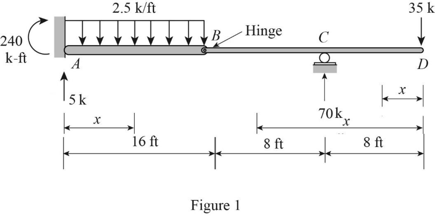
Find the reactions and moment at the supports:
Consider portion BCD, Summation of moments about B is equal to 0.
Summation of forces along y-direction is equal to 0.
Summation of moments about A is equal to 0.
Consider the virtual system.
Draw a diagram of beam without the given real loads. For deflection apply unit load at the point and in the desired direction.
For slope calculation, apply a unit couple at the point on the beam where the slope is desired.
Sketch the virtual system of the beam with unit couple at point D as shown in Figure 2.
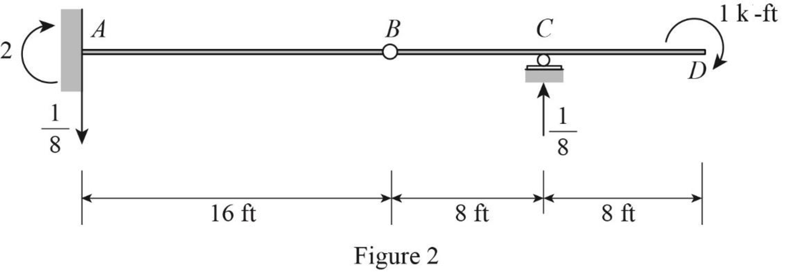
Let an equation expressing the variation of bending moment due to virtual couple be
Consider portion BCD, Summation of moments about B is equal to 0.
Summation of forces along y-direction is equal to 0.
Summation of moments about A is equal to 0.
Sketch the virtual system of the beam with unit load at point D as shown in Figure 3.
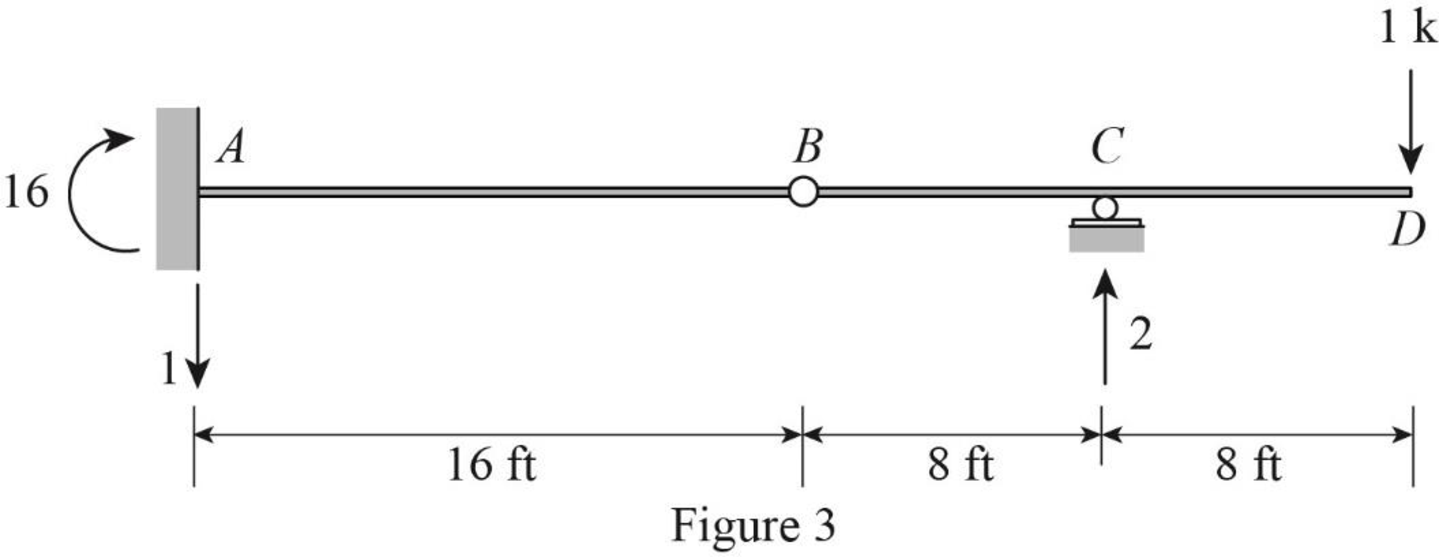
Let an equation expressing the variation of bending moment due to virtual load be
Consider portion BCD, Summation of moments about B is equal to 0.
Summation of forces along y-direction is equal to 0.
Summation of moments about A is equal to 0.
Find the equations for M,
| Segment | x-coordinate |
M |
|
| |
| Origin | Limits (m) | ||||
| DC | D | ||||
| CB | D | ||||
| AB | A | ||||
Find the slope at D using the virtual work expression:
Here, L is the length of the beam, E is the young’s modulus, and I is the moment of inertia.
Rearrange Equation (1) for the limits
Substitute
Substitute
Therefore, the slope at point D of the beam is
Find the deflection at D using the virtual work expression:
Rearrange Equation (2) for the limits
Substitute
Substitute
Therefore, the deflection at point D of the beam is
Want to see more full solutions like this?
Chapter 7 Solutions
Structural Analysis, Si Edition (mindtap Course List)


- A tension member made of L4x4x1/2 is connected to gusset plate with welds. Using E70electrode and ½ inch weld size, design the balanced weld lengths.( Use AISC manual, LRFD units)(Previous solution was incorrect)arrow_forwardQ1: determine the area of steel for the slab that rests on brick walls and is shown in the figure. Use the following data: f'c = 25 MPa, fy = 420 MPa, L.L. = 1.5 kN/m², D.L. = 3 kN/m² (without self-weight). Rate from (1 to 4) your ability to solve the problem 7 m 0.3 m 0.3 marrow_forwardA rigging job calls for lifting a structure that weighs 150 tons. Two cranes are available, one with a rated capacity of 85 tons and the other with a rated capacity of 120 tons. The total weight of the rigging required to make the lift is 15 tons, of which 10 tons is to be carried by the larger craneand 5 tons is to be carried by the smaller crane. If the cranes are to be loaded in proportion to their net capacities, what should be the approximate net load on the 120-ton crane?arrow_forward
- I need detailed help solving this exercise from homework of Engineering Mathematics II.I do not really understand how to do, please do it step by step, not that long but clear. Thank you!P.S.: Please do not use AI, thanks!arrow_forwardI need detailed help solving this exercise from homework of Engineering Mathematics II.I do not really understand how to do, please do it step by step, not that long but clear. Thank you!P.S.: Please do not use AI, thanks!arrow_forwarda) For the truss shown in Fig 2, determine the stiffness matrices of elements 2, 3 and 4 in the in the global co-ordinate system. Assume for each member A = 0.0015 m2 and E = 200 GPa. Indicate the degrees-of freedom in all the stiffness matrices. b) Determine the stiffness matrix of the whole truss in the global co-ordinate system. Clearly indicate the degrees-of freedom numbers in the stiffness matrix. c) Calculate all the nodal displacements and all the member forces of the truss.arrow_forward
- I want an answer very quickly, pleasearrow_forwardI want an answer very quickly, pleasearrow_forwardQ1/ Choose the correct answer for the following: 1- Cantilever retaining walls is suitable for retaining backfill about a- 8m d-4m b- 12m c- 2m e- Any height 2-The shear key is provided to a- Avoid friction behind the wall d- All of the above b- Improve appearance e- None of the above c- Increase passive resistance types of retaining wall may b- Semi-gravity retaining walls d-Counterfort retaining walls be classified as follows: 3- The common a- Gravity retaining walls walls c- Cantilever retaining e- All the mentioned 4-Related to Stability of RW, Which of the following does not represent a potential failure mode for a retaining wall? a-Bearing capacity failure of the foundation soil. b- Wall cracking due to thermal expansion. c- Excessive settlement due to weak soil layer. d- Shear failure within the foundation soil adjacent to the wall. e-Sliding along the base due to insufficient friction. 5- If the desired factor of safety against sliding is not met, which strategy is NOT a…arrow_forward
