
Basic Engineering Circuit Analysis
11th Edition
ISBN: 9781118992661
Author: Irwin, J. David, NELMS, R. M., 1939-
Publisher: Wiley,
expand_more
expand_more
format_list_bulleted
Concept explainers
Videos
Textbook Question
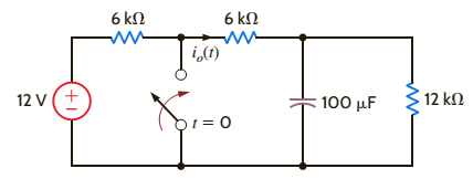
Chapter 7, Problem 2P
Use the differential equation approach to find
Expert Solution & Answer
Want to see the full answer?
Check out a sample textbook solution
Students have asked these similar questions
592
3.44 Use mesh analysis to obtain i, in the circuit of
Fig. 3.90.
ΖΩ
www
ww
ོག་
6 V
+
www
492
192
ww
3 A
+
12 V
Don't use ai to answer I will report you answer
2. If the Ce value in Fig. 11-7 is changed to 0.1 μF, is the output still a PWM
waveform? Explain.
C₁
0.014
C₂ 100
R₁ 300
HF
8
Vcc
4
reset
output
3
discharge
7
2
trigger
5 control
voltage
U₁ LM555
6
threshold
GND
ODUCT
R₂
10k
ww
Bo
+12 V
22
R3
1k
VR
5k
www
Re 300
C5 100
ww
8
Vcc
4 reset
output 3
2 trigger
7
discharge
ли
R7
10k
PWM
Output
threshold
C6
-0.014
5 control
voltage
GND
Rs
2k
CA
U2 LM555 1
100μ
C3
0.01
Audio lutput
Fig. 11-7 Pulse width modulator
Chapter 7 Solutions
Basic Engineering Circuit Analysis
Knowledge Booster


Learn more about
Need a deep-dive on the concept behind this application? Look no further. Learn more about this topic, electrical-engineering and related others by exploring similar questions and additional content below.Similar questions
- PROD 1. What is the function of VR, in Figs. 11-2 and 11-7. DL RO 0.014 +12V R₁ 1k ww Vin(+) 6 C₁ 0.1μ Audio input HH VRI Vin(-) 4 U1 HА741 10k ww R2 10k UCTS 0.01 μ -12V PWM output Fig. 11-2 The pulse width modulator based on μA741 +12 V ° C₂ 100 R₁ 300 Re 300 Cs 100 ww ww Vcc 4 reset 2 trigger 5 control voltage U₁ LM555 GND www R₂ T₁ 10k output 3 discharge Z Voc output 3 reset VR₁ 5k 2 trigger 7 discharge Ra 1k threshold 6 control 6 threshold voltage GND Rs CA U2 LM555 1 2k 100 Ca 0.01 Audio lutput www R7 10k O PWM C6 -0.014 Fig. 11-7 Pulse width modulator 11/9 Outputarrow_forwardPRO3. In a point of view of voltage polarity, what is the difference between the output PWM signals in experiments 11-1 and 11-2? H ICTS Experiment 11-1.. Pulse Width Modulator Using uA741 Experiment 11-2 Pulse Width Modulator Using LM555arrow_forward9.58 Using Fig. 9.65, design a problem to help other ed students better understand impedance combinations. Figure 8 65 ww C L R₁ www R2arrow_forward
- indicate which of the following switches may be used to control the loads listedarrow_forwardEXAMPLE 3.15 Consider a sinusoidal signal g(t) = Acos (2лfot+), where the parameters A, fo, and are nonzero constants representing the amplitude, frequency, and initial phase of the sinusoidal signal, respectively. Determine if it is an energy signal or a power signal or neither.arrow_forwardDo part a,b,c and earrow_forward
- 9.69 Find the equivalent admittance Yea of the circuit in Fig. 9.76. 2S 1 S -j3 S -j2 S www ww m m j5 S j1 S www 4 Sarrow_forward9.60 Obtain Zin for the circuit in Fig. 9.67. Zin 25 Ω www Figure 9.67 For Prob. 9.60. j152 m -j500 20 Ω 61 Find in the of Fia 0.68 m 30 Ω j102arrow_forwardFigure 9.58 For Prob. 9.51. 9.52 If V. =8/30° V in the circuit of Fig. 9.59, find I¸. Is 4 10 Ω Figure 9.59 For Prob. 9.52. www -j5Q 5 Ω ww j5Q Voarrow_forward
- 9.64 Find ZT and I in the circuit in Fig. 9.71. 30/90° V 492 www 602 www N ZT (+) Figure 9.71 For Prob. 9.64. -j10 18 Ωarrow_forward(b) 10 i dt + +6i(t) = 5 cos(5t + 22°) A dt 9.26 The loop equation for a series RLC circuit gives di+2i+ [ i dt = cos 21 A Assuming that the value of the integral at t=-00 is zero, find i(t) using the phasor method. 50 Figure 9arrow_forwardEXAMPLE 3.11 Classify the following systems into LTI and non-LTI systems: a) y(t)=x(t)cos(t), b) y(t) = (x(t+1)+x(t) +x(t − 1))/3, and c) y(t) = cos(x(t)).arrow_forward
arrow_back_ios
SEE MORE QUESTIONS
arrow_forward_ios
Recommended textbooks for you
 Power System Analysis and Design (MindTap Course ...Electrical EngineeringISBN:9781305632134Author:J. Duncan Glover, Thomas Overbye, Mulukutla S. SarmaPublisher:Cengage Learning
Power System Analysis and Design (MindTap Course ...
Electrical Engineering
ISBN:9781305632134
Author:J. Duncan Glover, Thomas Overbye, Mulukutla S. Sarma
Publisher:Cengage Learning
ENA 9.2(1)(En)(Alex) Sinusoids & Phasors - Explanation with Example 9.1 ,9.2 & PP 9.2; Author: Electrical Engineering Academy;https://www.youtube.com/watch?v=vX_LLNl-ZpU;License: Standard YouTube License, CC-BY
Electrical Engineering: Ch 10 Alternating Voltages & Phasors (8 of 82) What is a Phasor?; Author: Michel van Biezen;https://www.youtube.com/watch?v=2I1tF3ixNg0;License: Standard Youtube License