
Basic Engineering Circuit Analysis
11th Edition
ISBN: 9781118992661
Author: Irwin, J. David, NELMS, R. M., 1939-
Publisher: Wiley,
expand_more
expand_more
format_list_bulleted
Concept explainers
Videos
Textbook Question
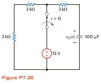
Chapter 7, Problem 26P
Find
Expert Solution & Answer
Want to see the full answer?
Check out a sample textbook solution
Students have asked these similar questions
solve by impedance
Consider the circuit diagram below. Compute a single equivalent impedance for this circuit for a source frequency of F = 60 Hz. Express your final answer as a complex impedance with rectangular coordinates. You must show your all your work for the complex math. Include a diagram of the equivalent circuit as part of your solution.
Consider the circuit diagram below. Compute a single equivalent impedance for this circuit for a source frequency of f = 165 Hz. Express your final answer as a phasor with polar coordinates. You must show your all your work for the complex math. Include a diagram of the equivalent circuit as part of your solution.
Chapter 7 Solutions
Basic Engineering Circuit Analysis
Additional Engineering Textbook Solutions
Find more solutions based on key concepts
Determine the slope and deflection of end A of the cantilevered beam. E = 200 GPa and I = 65.0(106) mm4. F122
Mechanics of Materials (10th Edition)
In the following exercises, write a program to carry out the task. The program should use variables for each of...
Introduction To Programming Using Visual Basic (11th Edition)
Can a package have any name you might want, or are there restrictions on what you can use for a package name? E...
Java: An Introduction to Problem Solving and Programming (8th Edition)
What four items should be identified when defining what a program is to do?
Starting Out With Visual Basic (8th Edition)
Write a loop that counts the number of space characters that appear in the String object str.
Starting Out with Java: From Control Structures through Data Structures (4th Edition) (What's New in Computer Science)
Largest Number Assume that a file containing a series of integers is named numbers.dat and exists on the comput...
Starting Out with Programming Logic and Design (5th Edition) (What's New in Computer Science)
Knowledge Booster


Learn more about
Need a deep-dive on the concept behind this application? Look no further. Learn more about this topic, electrical-engineering and related others by exploring similar questions and additional content below.Similar questions
- Consider the circuit diagram below. Using mesh analysis, compute the currents (a) IR1, (b) IL1, and (c) IC1. Express your final answers as phasors using polar coordinates with phase angles measured in degrees. Your solution should include the circuit diagram redrawn to indicate these currents and their directions. You must solve the system of equations using MATLAB and include the code or commands you ran as part of your solution.arrow_forwarduse kvl to solvearrow_forwardR1 is 978 ohms R2 is 2150 ohms R3 is 4780 R1 is parallel to R2 and R2 is parallel to R3 and R1 and R3 are in seriesarrow_forward
- Q7 For the circuit shown in Fig. 2.20, the transistors are identical and have the following parameters: hfe = 50, hie = 1.1K, hre = 0, and hoe = 0. Calculate Auf, Rif and Rof. Ans: 45.4; 112 KQ; 129. 25 V 10k 47k 4.7k Vo 150k w Vs 47k 4.7k W 22 5μF 33k 50uF 50μF 4.7k 4.7k R₁ Rof Rif R1000 Fig. 2.20 Circuit for Q7.arrow_forwardQ6)) The transistors in the feedback amplifier shown are identical, and their h-parameters are.. hie = 1.1k, hfe = 50, hre=o, and hoe = 0. Calculate Auf, Rif and Rof. {Ans: 6031583; 4. Kor. Is 4 4.7 k www 4.7k 91k 4.7k 91k 10k 1k. 10k 21000 4.7k w 15k Fig. 2.19 Circuit for Q6.arrow_forwardQ5 For the circuit shown in Fig. 2.18, hie =1.1 KQ, hfe =50. Find Avf, Rif and Rof Ans: -3.2; 193 ; 728 N. Vcc Vs Rs=10kQ Re=4KQ RF - = 40ΚΩ www Fig. 2.18 Circuit for Qs.arrow_forward
- Sheet No.2 Qi For the source follower shown in Fig. 2.14, Ipss =16 mA, V₂ =-4V, and VGsQ=-2.86 V. Find Avf, Rif and Rof. Assume rd is high. Ans: 0.833; ∞0; 365.7 . VDD Vo Vs R = 2.2 k Fig. 2.14 Circuit for Qi.arrow_forwardQ4 For the circuit shown in Fig. 2.17, he-100, he -1KQ. Find A, A, R and Rof- Ans:-100; -5; 100 K; 250K. Voc RB = 100 k R.=5k Vs Rs 500 R. = 1 kn Fig. 2.17 Circuit for Quarrow_forwardQ3 The circuit of Fig. 2.16 is to have Af = -1 mA/V, D=1+ BA=50, a voltage gain of -4, Rs = 1KQ, and hfe = 150. Find RL, Re, Rif and Rof. Ans: 4 KN; 980 ; 150 KN; ∞. Vcc RL Vs -OV +11 Fig. 2.16 Circuit for Q3.arrow_forward
- Q2 For the circuit shown in Fig. 2.15 hfe =150, hie =1KQ. Find Avf and Rif. Ans: 0.986; 152 KN. Vee R=4k2 Rs 1kQ Vo V, VR=1 KQ Fig. 2.15 Circuit for Q2-arrow_forwardR1 is 978 ohms, R2 is 2150 ohms R3 is 4780 ohmsarrow_forwardPleasw draw the block diagram, don't type out what it could look like. Draw it. Thank youarrow_forward
arrow_back_ios
SEE MORE QUESTIONS
arrow_forward_ios
Recommended textbooks for you
 Power System Analysis and Design (MindTap Course ...Electrical EngineeringISBN:9781305632134Author:J. Duncan Glover, Thomas Overbye, Mulukutla S. SarmaPublisher:Cengage Learning
Power System Analysis and Design (MindTap Course ...
Electrical Engineering
ISBN:9781305632134
Author:J. Duncan Glover, Thomas Overbye, Mulukutla S. Sarma
Publisher:Cengage Learning
ENA 9.2(1)(En)(Alex) Sinusoids & Phasors - Explanation with Example 9.1 ,9.2 & PP 9.2; Author: Electrical Engineering Academy;https://www.youtube.com/watch?v=vX_LLNl-ZpU;License: Standard YouTube License, CC-BY
Electrical Engineering: Ch 10 Alternating Voltages & Phasors (8 of 82) What is a Phasor?; Author: Michel van Biezen;https://www.youtube.com/watch?v=2I1tF3ixNg0;License: Standard Youtube License