
Concept explainers
Videos
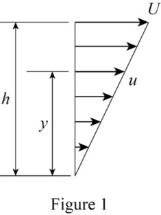
The rate of rotation of a fluid element and the shear strain rate of the element located at y.
Explanation of Solution
Draw the schematic representation of velocity distribution as in Figure (1).
Calculation:
Consider the steady flow of an ideal fluid. According to the velocity profile in Figure 1,
Here, h is the depth of water below the top plate and U is the constant velocity of the top plate.
The velocity, v, perpendicular to the direction of flow is zero.
Write the expression for the rate of rotation of a fluid element.
Here,
Substitute
The negative value of the rate of rotation represents an anticlockwise rotation.
Write the mathematical expression for the rate of shear strain.
Therefore, the rate of rotation of a fluid element is
Want to see more full solutions like this?
Chapter 7 Solutions
FLUID MECHANICS-EBOOK>I<


- Problem 2: An athlete, starting from rest, pulls handle A to the left with a constant force of P = 150 [N]. Knowing that after the handle A has been pulled 0.5 [m], its velocity is 5 [m/s] to the left, determine: a) A position constraint equation using the given coordinate system. b) An acceleration constraint equation. c) The acceleration of A using kinematics equations. d) The acceleration of B using your constraint equation. e) How much weight (magnitude) the athlete is lifting in pounds using Newton's 2nd Law. You must draw a FBD and KD of the circled assembly, assuming the pulleys are massless. Note: 1 [lbf] = 4.448 [N]. ХА Увarrow_forwardProblem 1: For each of the following images, draw a complete FBD and KD for the specified objects. Then write the equations of motion using variables for all unknowns (e.g., mass, friction coefficient, etc.), plugging in kinematic expressions and simplifying where appropriate. Assume motion in all cases, so any friction would be kinetic. M (a) Blocks A & B (Be careful with acceleration of B relative to accelerating block A) 30° (b) Block A being pulled up my motor M (use rotated rectangular coordinate system) 20° (c) Ball at C, top of swing (use path coordinates) (d) Parasailer/Person (use polar coordinates)arrow_forwardwhere M1=0.41m, M2=1.8m, M3=0.56m, please use bernoulis equation where necessary and The solutions should include, but not be limited to, the equations used tosolve the problems, the charts used to solve the problems, detailed working,choice of variables, the control volume considered, justification anddiscussion of results etc.If determining the friction factor, the use of both Moody chart and empiricalequations should be used to verify the validity of the value.arrow_forward
- Q3. The attachment shown in Fig.2 is made of 1040 HR. Design the weldment (give the pattern, electrode number, type of weld, length of weld, and leg size). All dimensions in mm 120 Fig.2 12 17 b =7.5 5 kN 60 60°arrow_forward15 mm DA 100 mm 50 mm Assuming the load applied P 80 kN. Determine the maximum stress in the bar shown assuming the diameter of the whole A is DA = 25 mm.arrow_forwarduse engineering economic tables, show full solutionarrow_forward
- Do not use chatgpt. I need quick handwritten solution.arrow_forwardSolve this problem and show all of the workarrow_forwardarch Moving to año Question 5 The head-vs-capacity curves for two centrifugal pumps A and B are shown below: Which of the following is a correct statement at a flow rate of 600 ft3/min? Assuming a pump efficiency of 80%. Head [ft] 50 45. 40 CHE 35. 30 25 20 PR 64°F Cloudy 4arrow_forward
- I need help with a MATLAB code. I am trying to implement algorithm 3 and 4 as shown in the image. I am getting some size errors. Can you help me fix the code. clc; clear all; % Define initial conditions and parameters r0 = [1000, 0, 0]; % Initial position in meters v0 = [0, 10, 0]; % Initial velocity in m/s m0 = 1000; % Initial mass in kg z0 = log(m0); % Initial mass logarithm a0 = [0, 0, 1]; % Initial thrust direction in m/s^2 (thrust in z-direction) sigma0 = 0.1; % Initial thrust magnitude divided by mass % Initial state vector x0 = [r0, v0, z0] x0 = [r0, v0, z0]; % Initial control input u0 = [a0, sigma0] u0 = [a0, sigma0]; % Time span for integration t0 = 0; % Initial time tf = 10; % Final time N = 100; % Number of time steps dt = (tf - t0) / N; % Time step size t_span = linspace(t0, tf, N); % Discretized time vector % Solve the system of equations using ode45 [t, Y] = ode45(@(t, Y) EoMwithDiscreteMatrix(t, Y, u0, x0, t0, tf), t_span, x0); % Compute the matrices A_k,…arrow_forwardQ2) Determine the thickness of weld (h) for the figure shown below. when the Su= 410 MPa and factor of safety of 2. COR 50 200 60 F=2000Narrow_forwardPlease draw front, top and side view, in AutoCAD both of themarrow_forward
 Elements Of ElectromagneticsMechanical EngineeringISBN:9780190698614Author:Sadiku, Matthew N. O.Publisher:Oxford University Press
 Mechanics of Materials (10th Edition)Mechanical EngineeringISBN:9780134319650Author:Russell C. HibbelerPublisher:PEARSON
 Thermodynamics: An Engineering ApproachMechanical EngineeringISBN:9781259822674Author:Yunus A. Cengel Dr., Michael A. BolesPublisher:McGraw-Hill Education
 Control Systems EngineeringMechanical EngineeringISBN:9781118170519Author:Norman S. NisePublisher:WILEY
 Mechanics of Materials (MindTap Course List)Mechanical EngineeringISBN:9781337093347Author:Barry J. Goodno, James M. GerePublisher:Cengage Learning
 Engineering Mechanics: StaticsMechanical EngineeringISBN:9781118807330Author:James L. Meriam, L. G. Kraige, J. N. BoltonPublisher:WILEY