
Videos
In each case, identify any two-force members, and then draw the free body diagrams of each member of the frame.
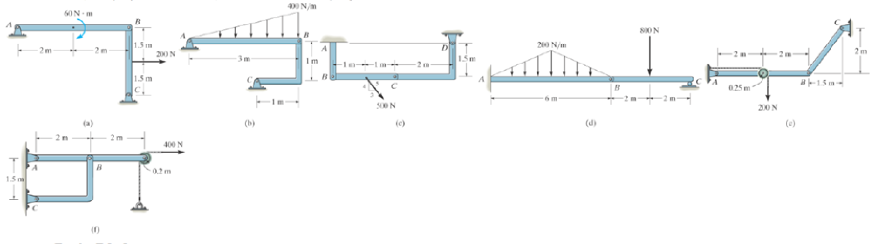
Prob. P6-3
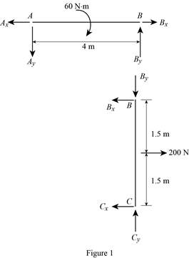
(a)
To identify and draw: The two force members and the free body diagrams of each member of the frame.
Explanation of Solution
Assumptions:
- Consider the state of member as tension where the force is pulling the member and as compression where the force is pushing the member.
- Consider the force indicating right side as positive and left side as negative in horizontal components of forces.
- Consider the force indicating upside is taken as positive and downside as negative in vertical components of forces.
Show the free body diagram of the member of the frame as in Figure (1).
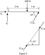
(b)
To identify and draw: The two force members and the free body diagrams of each member of the frame.
Explanation of Solution
Assumptions:
- Consider the state of member as tension where the force is pulling the member and as compression where the force is pushing the member.
- Consider the force indicating right side as positive and left side as negative in horizontal components of forces.
- Consider the force indicating upside is taken as positive and downside as negative in vertical components of forces.
The member CB is a two force member.
Show the free body diagram of the members of the frame as in Figure (2).
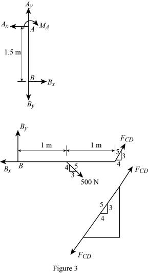
(c)
To identify and draw: The two force members and the free body diagrams of each member of the frame.
Explanation of Solution
Assumptions:
- Consider the state of member as tension where the force is pulling the member and as compression where the force is pushing the member.
- Consider the force indicating right side as positive and left side as negative in horizontal components of forces.
- Consider the force indicating upside is taken as positive and downside as negative in vertical components of forces.
The member CD is a two force member.
Show the free body diagram of the members of the frame as in Figure (3).
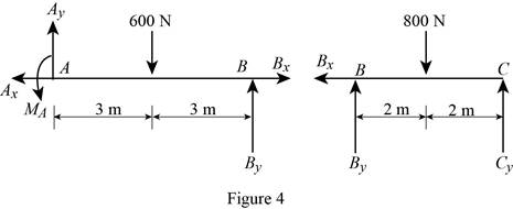
(d)
To identify and draw: The two force members and the free body diagrams of each member of the frame.
Explanation of Solution
Assumptions:
- Consider the state of member as tension where the force is pulling the member and as compression where the force is pushing the member.
- Consider the force indicating right side as positive and left side as negative in horizontal components of forces.
- Consider the force indicating upside is taken as positive and downside as negative in vertical components of forces.
Show the free body diagram of the members of the frame as in Figure (4).
(e)
To identify and draw: The two force members and the free body diagrams of each member of the frame.
Explanation of Solution
Assumptions:
- Consider the state of member as tension where the force is pulling the member and as compression where the force is pushing the member.
- Consider the force indicating right side as positive and left side as negative in horizontal components of forces.
- Consider the force indicating upside is taken as positive and downside as negative in vertical components of forces.
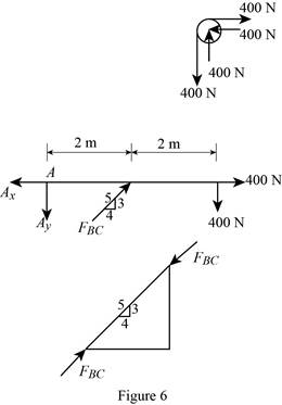
The member BC is a two force member.
Show the free body diagram of the members of the frame as in Figure (5).

(f)
To identify and draw: The two force members and the free body diagrams of each member of the frame.
Explanation of Solution
Assumptions:
- Consider the state of member as tension where the force is pulling the member and as compression where the force is pushing the member.
- Consider the force indicating right side as positive and left side as negative in horizontal components of forces.
- Consider the force indicating upside is taken as positive and downside as negative in vertical components of forces.
The member BC is a two force member.
Show the free body diagram of the members of the frame as in Figure (5).
Want to see more full solutions like this?
Chapter 6 Solutions
ENGINEERING MECHANICS Â?? STATICS
Additional Engineering Textbook Solutions
Starting Out with Programming Logic and Design (5th Edition) (What's New in Computer Science)
Starting Out with Python (4th Edition)
Starting Out with Java: From Control Structures through Objects (7th Edition) (What's New in Computer Science)
Mechanics of Materials (10th Edition)
Degarmo's Materials And Processes In Manufacturing
Java: An Introduction to Problem Solving and Programming (8th Edition)


- In using the bolt cutter shown, a worker applies two forces P to the handles. If the magnitude ofP is 500 N, determine the magnitude of the forces exerted by the cutter on the boltarrow_forwardArterioles bifurcate (i.e., split) into capillaries in the circulatory system. Blood flows at a velocity of 20 cm/s through an arteriole with a diameter of 0.20 cm. This vessel bifurcates into two vessels: one with a diameter of 0.17 cm and a blood flow velocity of 18 cm/sec, and one with a diameter of 0.15 cm. Each of these two vessels splits again. The 0.17-cm diameter vessel splits into two vessels, each with a diameter of 0.15 cm. The 0.15-cm diameter vessel splits into two vessels, each with a diameter of 0.12 cm. Determine the mass flow rate and velocity of blood in each of the four vessels at the end of the arteriole bifurcations. You may need to set up several systems, each with a different system boundary, in order to solve this problem.arrow_forward6) Draw a Front, side and Top view for the following objects: p.s. you don't need to label the alphabet ISOMETRIC PICTORIAL VIEW K R C B E R D 0 Aarrow_forward
- Please draw the front top and side view for the following objectarrow_forwardDraw the top viewarrow_forwardSuppose that a steel of eutectoid composition is cooled to 675°C (1250°F) from 760°C (1400°F) in less than 0.5 s and held at this temperature. (a) How long will it take for the austenite-topearlite reaction to go to 50% completion? To 100% completion? (b) Estimate the hardness of the alloy that has completely transformed to pearlite.arrow_forward
- Problem 2: Determine the components of the reaction at point B (Please use paper sheet + FBD ,don't use chatgpt) MECHANICAL ENGGarrow_forwardARL040_AE_Kn_2of3... Dor Question 4. A two-throw crankshaft has masses distributed as shown: RAH 90 rpm A TRAV B Re Rev M₁ = 15kg; M₂ = 12kg L = 950mm; 1, 350mm; 1₁ = 600mm; 0₁ = 90°; 02=0°; r₁ = 300mm; r250mm The crankshaft is to be balanced by attaching masses at radii of 300 mm and rotating in planes 150 mm outside the planes of number one and number two cranks. Determine the magnitude and angular position of the balance masses. Answer 4.arrow_forwardFEAarrow_forward
- Finite Element Analysisarrow_forwardan experimental research station is constructed on a concrete slab floor. The heat loss from the floor slab is significant, given the cold environment, and is measured to be 5 kW. The edges of the floor slab are insulated with a 60 mm thickness of cellular glass insulation. The width of this insulation at the floor slab is 0.9 m. To avoid excessive fuel consumption, the station air temperature is maintained at a slightly cool temperature of 18ºC. The station is constructed in a square shape, to keep the surface area to volume ratio low; the horizontal dimensions of the floor of the station are 20 m by 20 m. The number of occupants in the research station varies between 5 and 20, depending on the research workload.a) Determine the design outdoor temperature that was used in designing the research station.b) If the floor dimensions of the station are changed to 15 m by 25 m, would the design outdoor temperature that was used in designing the research station from part (a) change? If so,…arrow_forwardFinite element analysisarrow_forward
 Elements Of ElectromagneticsMechanical EngineeringISBN:9780190698614Author:Sadiku, Matthew N. O.Publisher:Oxford University Press
 Mechanics of Materials (10th Edition)Mechanical EngineeringISBN:9780134319650Author:Russell C. HibbelerPublisher:PEARSON
 Thermodynamics: An Engineering ApproachMechanical EngineeringISBN:9781259822674Author:Yunus A. Cengel Dr., Michael A. BolesPublisher:McGraw-Hill Education
 Control Systems EngineeringMechanical EngineeringISBN:9781118170519Author:Norman S. NisePublisher:WILEY
 Mechanics of Materials (MindTap Course List)Mechanical EngineeringISBN:9781337093347Author:Barry J. Goodno, James M. GerePublisher:Cengage Learning
 Engineering Mechanics: StaticsMechanical EngineeringISBN:9781118807330Author:James L. Meriam, L. G. Kraige, J. N. BoltonPublisher:WILEY