
Industrial Motor Control
7th Edition
ISBN: 9781133691808
Author: Stephen Herman
Publisher: Cengage Learning
expand_more
expand_more
format_list_bulleted
Videos
Question
Chapter 64, Problem 1RQ
To determine
The diagram for the schematic symbol for the TRIAC.
Expert Solution & Answer
Explanation of Solution
The TRIAC is the device that is used to control the AC power and they can swtich the high voltage and the large current over the both the cycle of the AC power. The TRIAC is also a three terminal bidirectional device.
Consider that the PNPN junction is connected in parallel to the NPNP junction is called the TRIAC.
The schematic symbol for the TRIAC is shown in Figure below.
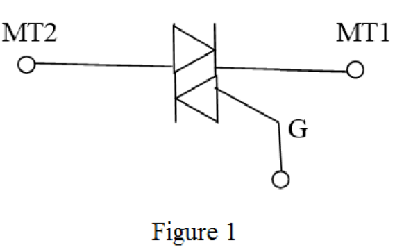
The symbol for triac is shown in Figure 1
Want to see more full solutions like this?
Subscribe now to access step-by-step solutions to millions of textbook problems written by subject matter experts!
Students have asked these similar questions
50 mm
12 mm
B
O
C
OA
300 mm
450 mm
E
PROBLEM 1.51
Each of the steel links AB and CD is connected to a support and to
member BCE by 25-mm-diameter steel pins acting in single shear.
Knowing that the ultimate shearing stress is 210 MPa for the steel
used in the pins and that the ultimate normal stress is 490 MPa for
the steel used in the links, determine the allowable load P if an
overall factor of safety of 3.0 is desired. (Note that the links are not
reinforced around the pin holes.)
3. A 15% magnesium chloride solution is flowing through a 5-nom sch 40 commercial steel pipe
at a rate of 325,000 lbm/h. The average temperature of the magnesium chloride solution as it flows
through the pipe is 10°F. Determine the convective heat transfer coefficient inside the pipe.
2. Jojoba oil is flowing through a ¾-nom stainless steel pipe at a flow rate of 1,850 lbm/h. After
the velocity profile in the pipe is fully developed, the oil enters a heater, as shown in Figure P5.7.
The length of the heater section is 5 ft. The properties of the jojoba oil at the average temperature
in the heater section are given in Table P5.7. Determine the convective heat transfer coefficient
inside the heater section of the
pipe.
¾ nom stainless steel pipe
Heater section
L=5ft
Fig. P5.7
TABLE P5.7
Thermophysical Properties of Jojoba Oil at the Average Temperature in the Heater
P
(lbm/ft³)
68.671
(Btu/lbm-R)
0.30339
μ
(lbm/ft-s)
0.012095
k
(Btu/h-ft-°F)
0.077424
Knowledge Booster


Learn more about
Need a deep-dive on the concept behind this application? Look no further. Learn more about this topic, mechanical-engineering and related others by exploring similar questions and additional content below.Similar questions
- 1. Water is flowing inside of a 3-std type K copper tube at a flow rate of 1.2 kg/s. The average temperature of the water is 50°C. Cold, dry air at a temperature of 5°C and atmospheric pressure flows outside of the tube in cross flow with a velocity of 85 m/s. Determine the UA product for this tube under clean conditions.arrow_forwardHints: Find the closed loop transfer function and then plot the step response for diFerentvalues of K in MATLAB. Show step response plot for different values of K. Auto Controls Show solutions and provide matlab code NO COPIED ANSWERS OR WILL REPORT!!!!arrow_forward37. The vertical shaft shown in Figure P12-37 is driven at a speed of 600 rpm with 4.0 hp entering through the bevel gear. Each of the two chain sprockets delivers 2.0 hp to the side to drive mixer blades in a chemical reactor vessel. The bevel gear has a diametral pitch of 5, a pitch diameter of 9.000 in, a face width of 1.31 in, and a pressure angle of 20°. Use SAE 4140 OQT 1000 steel for the shaft. See Chapter 10 for the methods for computing the forces on the bevel gear. Figure P12-37: P37-Bevel gear drive with two chain sprockets Each problem includes the following details: ■Design the complete shaft, including the specification of the overall geometry and the consideration of stress con- centration factors. The analysis would show the minimum acceptable diameter at each point on the shaft to be safe from the standpoint of strength. Homework Problems 12-24, 12-35, and 12-37 from textbook, done in spreadsheet form. Place drawings of the load, shear, and bending moment body diagrams…arrow_forward
- 35. The double-reduction, helical gear reducer shown in Figure P12-35 transmits 5.0 hp. Shaft 1 is the input, rotating at 1800 rpm and receiving power directly from an electric motor through a flexible coupling. Shaft 2 rotates at 900 rpm. Shaft 3 is the output, rotating at 300 rpm. A chain sprocket is mounted on the output shaft as shown and delivers the power upward. The data for the gears are given in Table 12-5. Each gear has a 1412° normal pressure angle and a 45° helix angle. The combinations of left- and right-hand helixes are arranged so that the axial forces oppose each other on shaft 2 as shown. Use SAE 4140 OQT 1200 for the shafts. Figure P12-35: P35-Double-reduction helical drive Each problem includes the following details: ■Design the complete shaft, including the specification of the overall geometry and the consideration of stress con- centration factors. The analysis would show the minimum acceptable diameter at each point on the shaft to be safe from the standpoint of…arrow_forwardConsider 0.65 kg of N2 at 300 K, 1 bar contained in a rigid tank connected by a valve to another rigid tank holding 0.3 kg of CO2 at 300 K, 1 bar. The valve is opened and gases are allowed to mix, achieving an equilibrium state at 290 K. Determine: (a) the volume of each tank, in m³. (b) the final pressure, in bar. (c) the magnitude of the heat transfer to or from the gases during the process, in kJ. (d) the entropy change of each gas and of the overall system, in kJ/K.arrow_forwardBài 1. Cho cơ hệ như hình 1. Hình biểu diễn lược đổ cơ hệ tại vị trí cân bằng tĩnh. Trục tọa độ Oy hướng theo phương chuyển động của vật 1, gốc O đặt tại vị trí cân bằng của vật 1(tức khi lò xo biến dạng tĩnh). Bỏ qua khối lượng của thanh số 3. Vật rắn 2 là pulley 2 tầng đồng chất có bán kính ngoài 21, bán kính trong I, bán kính quán tính đối với trục qua tâm P-1.5, khối lượng m:. Vật rắn 4 là thanh thắng đồng chất có khối lượng m, chiều dài 1. Cho các số liệu: m = 2kg, m= = 5kg, m = 4kg, k=40(N/cm), ! – 0.8(m),r=0.1(m). Điều kiện đầu y; =0.5 cm );j = 10 cm/s) . Giả sử hệ dao động bé, Vật rắn 2 chuyển động lăn không trượt trên mặt phẳng ngang. 1. Viết phương trình chuyển động của hệ. 2. Xác định tần số dao động tự do của hệ. 3. Xác định đáp ứng dao động tự do của hệ. dây dây 1 2r Hình 1 y 3 -2 I k www. -2arrow_forward
- Hints: Find the closed loop transfer function and then plot the step response for diFerentvalues of K in MATLAB. Show step response plot for different values of K. Auto Controls Show solutions and provide matlab code NO COPIED ANSWERS OR WILL REPORTarrow_forwardObtain the response of the system shown below for a parabolic or acceleration input r(t);where Auto Controls Show full solutionarrow_forwardProblem Statement A large plate of insulating material 8 cm thick has in it a 3 cm-diam hole, with axis normal to the surface. The temperature of the surroundings are 1800 K at one side of the plate and 400 K on the other side. Insulating plate D= 3 cm H= 8 cm Considering the sides of the hole to be black, (a) Draw a system of resistors that can be used to solve for the various heat transfer rates. For full credit you must label all "voltages", "currents," and resistances present. (b) Estimate the radiative heat transfer through the hole.arrow_forward
- Using MATLAB, plot the unit-step response curve for the following transfer function and Using MATLAB, obtain the rise time, peak time, maximum overshoot, and settling time. Auto Controls Provide codesarrow_forwardUse Routh's stability criterion to determine how many roots with positive real partsthe following equations have Auto Controls Show full solutionsarrow_forwardPlot the unit step and unit ramp response curve for the following closed loop transferfunction using MATLAB. Indicate clearly the input and output in your plot Auto Controls provide matlab codearrow_forward
arrow_back_ios
SEE MORE QUESTIONS
arrow_forward_ios
Recommended textbooks for you
 Understanding Motor ControlsMechanical EngineeringISBN:9781337798686Author:Stephen L. HermanPublisher:Delmar Cengage Learning
 Precision Machining Technology (MindTap Course Li...Mechanical EngineeringISBN:9781285444543Author:Peter J. Hoffman, Eric S. Hopewell, Brian JanesPublisher:Cengage Learning
Understanding Motor Controls
Mechanical Engineering
ISBN:9781337798686
Author:Stephen L. Herman
Publisher:Delmar Cengage Learning
Precision Machining Technology (MindTap Course Li...
Mechanical Engineering
ISBN:9781285444543
Author:Peter J. Hoffman, Eric S. Hopewell, Brian Janes
Publisher:Cengage Learning
Material Science, Phase Diagrams, Part 1; Author: Welt der Werkstoffe;https://www.youtube.com/watch?v=G83ZaoB3XCc;License: Standard Youtube License