
Concept explainers
The truss shown consists of nine members and is support by a ball-and-socket at B, a short link at C, and two short links at D. (a) Check that this truss is a simple truss, that completely constrained, and that the reactions at its suppo are statically determinate. (b) Determine the force in each member for P = (−1200 N)j and Q = 0.
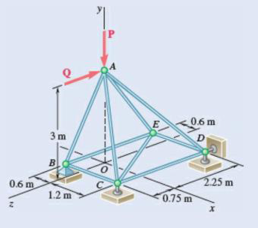
Fig. P6.39
(a)
Verify that the truss is a simple truss, completely constrained, and the reactions at the supports are statically determinate.
Answer to Problem 6.39P
The reactions at supports B, C, and D is
Explanation of Solution
Given information:
The value of the force P is
The value of the force Q is zero.
Calculation:
Show the free-body diagram of the truss as in Figure 1.
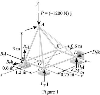
Find the vector coordinates by taking moment about point B.
Equate the coefficients of i to zero.
Equate the coefficients of j to zero.
Equate the coefficients of k to zero.
Substitute 300 N for
Resolve the force components in y-axis.
Substitute 300 N for
The unknown reactions can be calculated with the equilibrium equations. Therefore, the truss is statically determinate, completely constrained and simple truss.
Thus, the reactions at supports B, C, and D is
(b)
Find the force in each member of the truss.
Answer to Problem 6.39P
The force in the member AB is
The force in the member BC is
The force in the member BE is
The force in the member AC is
The force in the member CE is
The force in the member CD is
The force in the member AD is
The force in the member DE is
The force in the member AE is
Explanation of Solution
Show the free-body diagram of the joint B as in Figure 2.
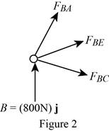
Resolve the force components as follows;
Write the vector value of
Find the scalar quantity of BA using the relation.
Find the force in the member AB as follows;
Substitute
Find the force in the member BC as follows;
Find the force in the member BE as follows;
Equate the coefficients of j to zero.
Equate the coefficients of i to zero.
Substitute –840 N for
Equate the coefficients of k to zero.
Substitute –840 N for
Therefore,
The force in the member AB is
The force in the member BC is
The force in the member BE is
Show the free-body diagram of the joint C as in Figure 3.
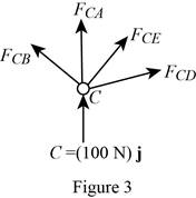
Resolve the force components as follows;
Write the vector value of
Find the scalar quantity of CA using the relation.
Find the force in the member AC as follows;
Substitute
Find the force in the member CB as follows;
Find the force in the member CD as follows;
Write the vector value of
Find the scalar quantity of CE using the relation.
Find the force in the member CE as follows;
Substitute
Equate the coefficients of j to zero.
Equate the coefficients of i to zero.
Substitute –110.6 N for
Equate the coefficients of k to zero.
Substitute –110.6 N for
Therefore,
The force in the member AC is
The force in the member CE is
The force in the member CD is
Show the free-body diagram of the joint D as in Figure 4.
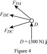
Resolve the force components as follows;
Write the vector value of
Find the scalar quantity of DA using the relation.
Find the force in the member AD as follows;
Substitute
Find the force in the member DC as follows;
Find the force in the member DE as follows;
Equate the coefficients of j to zero.
Equate the coefficients of i to zero.
Substitute –394 N for
Therefore,
The force in the member AD is
The force in the member DE is
Show the free-body diagram of the joint E as in figure 5.
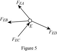
The member AE is not in the xz plane.
Therefore, the force in the member AE is
Want to see more full solutions like this?
Chapter 6 Solutions
VECTOR MECHANICS FOR ENGINEERS: STATICS
- Q10) Body A weighs 600 lb contact with smooth surfaces at D and E. Determine the tension in the cord and the forces acting on C on member BD, also calculate the reaction at B and F. Cable 6' 3' wwwarrow_forwardHelp ارجو مساعدتي في حل هذا السؤالarrow_forwardQ3: Find the resultant of the force system.arrow_forward
- Question 1 A three-blade propeller of a diameter of 2 m has an activity factor AF of 200 and its ratio of static thrust coefficient to static torque coefficient is 10. The propeller's integrated lift coefficient is 0.3.arrow_forward(L=6847 mm, q = 5331 N/mm, M = 1408549 N.mm, and El = 8.6 x 10¹⁴ N. mm²) X A ΕΙ B L Y Marrow_forwardCalculate the maximum shear stress Tmax at the selected element within the wall (Fig. Q3) if T = 26.7 KN.m, P = 23.6 MPa, t = 2.2 mm, R = 2 m. The following choices are provided in units of MPa and rounded to three decimal places. Select one: ○ 1.2681.818 O 2. 25745.455 O 3. 17163.636 O 4. 10727.273 ○ 5.5363.636arrow_forward
- If L-719.01 mm, = 7839.63 N/m³, the normal stress σ caused by self-weight at the location of the maximum normal stress in the bar can be calculated as (Please select the correct value of σ given in Pa and rounded to three decimal places.) Select one: ○ 1. 1409.193 2. 845.516 O 3. 11273.545 ○ 4.8455.159 ○ 5.4509.418 6. 2818.386 7.5636.772arrow_forwardTo calculate the rotation at Point B, a suitable virtual structure needs to be created. Which equation in the following choices most accurately represents the functional relationship between the bending moment, Mv2 ( Units: N.mm), of the virtual structure and the spatial coordinate x (Units: mm) if the applied unit virtual moment is clockwise? Select one: O 1. Mv2 1.000 O 2. Mv2=x+1.000 O 3. Mv2=x+0.000 4. Mv2 = -x-1.000 O 5. Mv2 -1.000 6. Mv2=-x+0.000arrow_forwardThe vertical deflection at Point B can be calculated as ( The following choices are provided in units of mm and rounded to three decimal places ; the downward deflection is negative and upward deflection is positive. ) Select one: 1. 1703.065 2. -1703.065 3. -2043.679 4.1362.452 5. -1362.452 6. 2043.679arrow_forward
 International Edition---engineering Mechanics: St...Mechanical EngineeringISBN:9781305501607Author:Andrew Pytel And Jaan KiusalaasPublisher:CENGAGE L
