
EBK MECHANICS OF MATERIALS
7th Edition
ISBN: 8220102804487
Author: BEER
Publisher: YUZU
expand_more
expand_more
format_list_bulleted
Concept explainers
Videos
Textbook Question
Chapter 6, Problem 99RP
A thin-walled beam of uniform thickness has the cross section shown. Determine the dimension b for which the shear center O of the cross section is located at the point indicated.
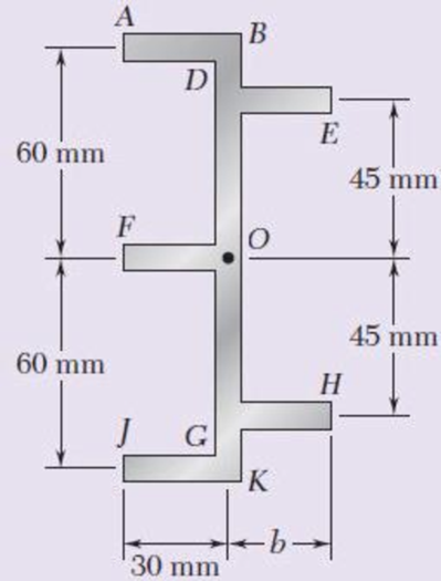
Fig. P6.99
Expert Solution & Answer
Want to see the full answer?
Check out a sample textbook solution
Students have asked these similar questions
can you please help me perform Visual Inspection and Fractography of the attatched image: Preliminary examination to identify the fracture origin, suspected fatigue striation, and corrosion evidences.
can you please help[ me conduct Causal Analysis (FTA) on the scenario attatched: FTA diagram which is a fault tree analysis diagram will be used to gain an overview of the entire path of failure from root cause to the top event (i.e., the swing’s detachment) and to identify interactions between misuse, material decay and inspection errors.
hi can you please help me in finding the stress intensity factor using a k-calcluator for the scenario attathced in the images.
Chapter 6 Solutions
EBK MECHANICS OF MATERIALS
Ch. 6.2 - Three full-size 50 100-mm boards are nailed...Ch. 6.2 - For the built-up beam of Prob. 6.1, determine the...Ch. 6.2 - Three boards, each 2 in. thick, are nailed...Ch. 6.2 - A square box beam is made of two 20 80-mm planks...Ch. 6.2 - The American Standard rolled-steel beam shown has...Ch. 6.2 - The beam shown is fabricated by connecting two...Ch. 6.2 - A column is fabricated by connecting the...Ch. 6.2 - The composite beam shown is fabricated by...Ch. 6.2 - 6.9 through 6.12 For beam and loading shown,...Ch. 6.2 - 6.9 through 6.12 For beam and loading shown,...
Ch. 6.2 - 6.9 through 6.12 For beam and loading shown,...Ch. 6.2 - 6.9 through 6.12 For beam and loading shown,...Ch. 6.2 - 6.13 and 6.14 For a beam having the cross section...Ch. 6.2 - 6.13 and 6.14 For a beam having the cross section...Ch. 6.2 - For a timber beam having the cross section shown,...Ch. 6.2 - Two steel plates of 12 220-mm rectangular cross...Ch. 6.2 - Two W8 31 rolled sections may be welded at A and...Ch. 6.2 - For the beam and. loading shown, determine the...Ch. 6.2 - Fig. P6.19 6.19 A timber beam AB of length L and...Ch. 6.2 - A timber beam AB of Length L and rectangular cross...Ch. 6.2 - 6.21 and 6.22 For the beam and loading shown,...Ch. 6.2 - 6.21 and 6.22 For the beam and loading shown,...Ch. 6.2 - 6.23 and 6.24 For the beam and loading shown,...Ch. 6.2 - 6.23 and 6.24 For the beam and loading shown,...Ch. 6.2 - 6.25 through 6.28 A beam having the cross section...Ch. 6.2 - 6.25 through 6.28 A beam having the cross section...Ch. 6.2 - Prob. 27PCh. 6.2 - 6.25 through 6.28 A beam having the cross section...Ch. 6.5 - The built-up timber beam shown is subjected to a...Ch. 6.5 - The built-up beam shown is made by gluing together...Ch. 6.5 - The built-up beam was made by gluing together...Ch. 6.5 - Several wooden planks are glued together to form...Ch. 6.5 - The built-up wooden beam shown is subjected to a...Ch. 6.5 - Knowing that a W360 122 rolled-steel beam is...Ch. 6.5 - 6.35 and 6.36 An extruded aluminum beam has the...Ch. 6.5 - 6.35 and 6.36 An extruded aluminum beam has the...Ch. 6.5 - Knowing that a given vertical shear V causes a...Ch. 6.5 - The vertical shear is 1200 lb in a beam having the...Ch. 6.5 - The vertical shear is 1200 lb in a beam having the...Ch. 6.5 - 6.40 and 6.47 The extruded aluminum beam has a...Ch. 6.5 - Prob. 41PCh. 6.5 - Prob. 42PCh. 6.5 - Three planks are connected as shown by bolts of...Ch. 6.5 - A beam consists of three planks connected as shown...Ch. 6.5 - A beam consists of five planks of 1.5 6-in. cross...Ch. 6.5 - Four L102 102 9.5 steel angle shapes and a 12 ...Ch. 6.5 - A plate of 14-in. thickness is corrugated as shown...Ch. 6.5 - Prob. 48PCh. 6.5 - An extruded beam has the cross section shown and a...Ch. 6.5 - Prob. 50PCh. 6.5 - The design of a beam calls for connecting two...Ch. 6.5 - The cross section of an extruded beam is a hollow...Ch. 6.5 - Prob. 53PCh. 6.5 - Prob. 54PCh. 6.5 - Prob. 55PCh. 6.5 - 6.56 and 6.57 A composite beam is made by...Ch. 6.5 - 6.56 and 6.57 A composite beam is made by...Ch. 6.5 - Prob. 58PCh. 6.5 - Prob. 59PCh. 6.5 - Prob. 60PCh. 6.6 - 6.61 through 6.64 Determine the location of the...Ch. 6.6 - 6.61 through 6.64 Determine the location of the...Ch. 6.6 - 6.61 through 6.64 Determine the location of the...Ch. 6.6 - Prob. 64PCh. 6.6 - 6.65 through 6.68 An extruded beam has the cross...Ch. 6.6 - 6.65 through 6.68 An extruded beam has the cross...Ch. 6.6 - 6.65 through 6.68 An extruded beam has the cross...Ch. 6.6 - 6.65 through 6.68 An extruded beam has the cross...Ch. 6.6 - 6.69 through 6.74 Determine the location of the...Ch. 6.6 - Prob. 70PCh. 6.6 - Prob. 71PCh. 6.6 - Prob. 72PCh. 6.6 - Prob. 73PCh. 6.6 - Prob. 74PCh. 6.6 - Prob. 75PCh. 6.6 - 6.75 and 6.76 A thin-walled beam has the cross...Ch. 6.6 - 6.77 and 6.78 A thin-walled beam of uniform...Ch. 6.6 - Prob. 78PCh. 6.6 - Prob. 79PCh. 6.6 - Prob. 80PCh. 6.6 - Prob. 81PCh. 6.6 - Prob. 82PCh. 6.6 - Prob. 83PCh. 6.6 - Prob. 84PCh. 6.6 - Prob. 85PCh. 6.6 - Solve Prob. 6.85, assuming that the thickness of...Ch. 6.6 - Prob. 87PCh. 6.6 - Prob. 88PCh. 6 - Three boards are nailed together to form the beam...Ch. 6 - For the beam and loading shown, consider section...Ch. 6 - For the wide-flange beam with the loading shown,...Ch. 6 - For the beam and loading shown, consider section...Ch. 6 - The built-up timber beam is subjected to a 1500-lb...Ch. 6 - Knowing that a given vertical shear V causes a...Ch. 6 - Three planks are connected as shown by bolts of...Ch. 6 - Three 1 18-in. steel plates are bolted to four L6...Ch. 6 - The composite beam shown is made by welding C200 ...Ch. 6 - Prob. 98RPCh. 6 - A thin-walled beam of uniform thickness has the...Ch. 6 - Determine the location of the shear center O of a...
Knowledge Booster


Learn more about
Need a deep-dive on the concept behind this application? Look no further. Learn more about this topic, mechanical-engineering and related others by exploring similar questions and additional content below.Similar questions
- Hi, can you please help me .Identify and justify suitable analytical techniques of the scenario below, bearing in mind the kinds of information being handled to reach a conclusion (methodology). A child swing set was discovered to have failed at the fixing at the top of the chains connecting the seat to the top of the swing set. A 12 mm threaded steel bolt, connecting the shackle to the top beam, failed at the start of the threaded region on the linkage closest to the outside side of the swing set . The linkage and bolts were made of electro galvanised mild steel . The rigid bar chain alternatives and fixings were of the same material and appeared to be fitted in accordance with guidelines. The yield strength of the steel used is 260 MPa and the UTS is 380 MPa. The bolt that failed was threaded using a standard thread with a pitch (distance between threads) of 1.75 mm and a depth of approximately 1.1 mm. The swing set in question had been assigned to ‘toddlers’ with the application of…arrow_forwardHi, can you please define and calculate the failure mode of the linkage that failed on the swing (images added) : A child swing set was discovered to have failed at the fixing at the top of the chains connecting the seat to the top of the swing set. A 12 mm threaded steel bolt, connecting the shackle to the top beam, failed at the start of the threaded region on the linkage closest to the outside side of the swing set . The linkage and bolts were made of electro galvanised mild steel . The rigid bar chain alternatives and fixings were of the same material and appeared to be fitted in accordance with guidelines. The yield strength of the steel used is 260 MPa and the UTS is 380 MPa. The bolt that failed was threaded using a standard thread with a pitch (distance between threads) of 1.75 mm and a depth of approximately 1.1 mm. The swing set in question had been assigned to ‘toddlers’ with the application of a caged-type seat. However, the location was within the play area not…arrow_forwardPage 11-68. The rectangular plate shown is subjected to a uniaxial stress of 2000 psi. Compute the shear stress and the tensile developed on a plane forming an angle of 30° with the longitud axis of the member. (Hint: Assume a cross-sectional area of unity) 2000 psi 2000 psi hparrow_forward
- 11-70. A shear stress (pure shear) of 5000 psi exists on an element. (a) Determine the maximum tensile and compressive stresses caused in the element due to this shear. (b) Sketch the element showing the planes on which the maximum tensile and compressive stresses act.arrow_forward11-20. An aluminum specimen of circular cross section, 0.50 in. in diameter, ruptured under a tensile load of 12,000 lb. The plane of failure was found to be at 48° with a plane perpendicular to the longitudinal axis of the specimen. (a) Compute the shear stress on the failure plane. (b) Compute the maximum tensile stress. (c) Compute the tensile stress on the failure plane. hparrow_forwardA long flat steel bar 13 mm thick and 120 mm wide has semicircular grooves as shown and carries a tensile load of 50 kN Determine the maximum stress if plate r= 8mm r=21mm r=38mmarrow_forward
- Problem 13: F₁ = A =250 N 30% Determine the moment of each of the three forces about point B. F₂ = 300 N 60° 2 m -3 m B 4 m F3=500 Narrow_forward3 kN 3 kN 1.8 kN/m 80 mm B 300 mm D an 1.5 m-1.5 m--1.5 m- PROBLEM 5.47 Using the method of Sec. 5.2, solve Prob. 5.16 PROBLEM 5.16 For the beam and loading shown, determine the maximum normal stress due to bending on a transverse section at C.arrow_forward300 mm 3 kN 3 kN 450 N-m D E 200 mm 300 mm PROBLEM 5.12 Draw the shear and bending-moment diagrams for the beam and loading shown, and determine the maximum absolute value (a) of the shear, (b) of the bending moment.arrow_forward
- CORRECT AND DETAILED SOLUTION WITH FBD ONLY. I WILL UPVOTE THANK YOU. CORRECT ANSWER IS ALREADY PROVIDED. I REALLY NEED FBD. The cantilevered spandrel beam shown whose depth tapers from d1 to d2, has a constant width of 120mm. It carries a triangularly distributed end reaction.Given: d1 = 600 mm, d2 = 120 mm, L = 1 m, w = 100 kN/m1. Calculate the maximum flexural stress at the support, in kN-m.2. Determine the distance (m), from the free end, of the section with maximum flexural stress.3. Determine the maximum flexural stress in the beam, in MPa.ANSWERS: (1) 4.630 MPa; (2) 905.8688 m; (3) 4.65 MPaarrow_forwardCORRECT AND DETAILED SOLUTION WITH FBD ONLY. I WILL UPVOTE THANK YOU. CORRECT ANSWER IS ALREADY PROVIDED. I REALLY NEED FBD A concrete wall retains water as shown. Assume that the wall is fixed at the base. Given: H = 3 m, t = 0.5m, Concrete unit weight = 23 kN/m3Unit weight of water = 9.81 kN/m3(Hint: The pressure of water is linearly increasing from the surface to the bottom with intensity 9.81d.)1. Find the maximum compressive stress (MPa) at the base of the wall if the water reaches the top.2. If the maximum compressive stress at the base of the wall is not to exceed 0.40 MPa, what is the maximum allowable depth(m) of the water?3. If the tensile stress at the base is zero, what is the maximum allowable depth (m) of the water?ANSWERS: (1) 1.13 MPa, (2) 2.0 m, (3) 1.20 marrow_forwardCORRECT AND DETAILED SOLUTION WITH FBD ONLY. I WILL UPVOTE THANK YOU. CORRECT ANSWER IS ALREADY PROVIDED. I NEED FBD A short plate is attached to the center of the shaft as shown. The bottom of the shaft is fixed to the ground.Given: a = 75 mm, h = 125 mm, D = 38 mmP1 = 24 kN, P2 = 28 kN1. Calculate the maximum torsional stress in the shaft, in MPa.2. Calculate the maximum flexural stress in the shaft, in MPa.3. Calculate the maximum horizontal shear stress in the shaft, in MPa.ANSWERS: (1) 167.07 MPa; (2) 679.77 MPa; (3) 28.22 MPaarrow_forward
arrow_back_ios
SEE MORE QUESTIONS
arrow_forward_ios
Recommended textbooks for you
 Elements Of ElectromagneticsMechanical EngineeringISBN:9780190698614Author:Sadiku, Matthew N. O.Publisher:Oxford University Press
 Mechanics of Materials (10th Edition)Mechanical EngineeringISBN:9780134319650Author:Russell C. HibbelerPublisher:PEARSON
 Thermodynamics: An Engineering ApproachMechanical EngineeringISBN:9781259822674Author:Yunus A. Cengel Dr., Michael A. BolesPublisher:McGraw-Hill Education
 Control Systems EngineeringMechanical EngineeringISBN:9781118170519Author:Norman S. NisePublisher:WILEY
 Mechanics of Materials (MindTap Course List)Mechanical EngineeringISBN:9781337093347Author:Barry J. Goodno, James M. GerePublisher:Cengage Learning
 Engineering Mechanics: StaticsMechanical EngineeringISBN:9781118807330Author:James L. Meriam, L. G. Kraige, J. N. BoltonPublisher:WILEY
Elements Of Electromagnetics
Mechanical Engineering
ISBN:9780190698614
Author:Sadiku, Matthew N. O.
Publisher:Oxford University Press
Mechanics of Materials (10th Edition)
Mechanical Engineering
ISBN:9780134319650
Author:Russell C. Hibbeler
Publisher:PEARSON
Thermodynamics: An Engineering Approach
Mechanical Engineering
ISBN:9781259822674
Author:Yunus A. Cengel Dr., Michael A. Boles
Publisher:McGraw-Hill Education
Control Systems Engineering
Mechanical Engineering
ISBN:9781118170519
Author:Norman S. Nise
Publisher:WILEY
Mechanics of Materials (MindTap Course List)
Mechanical Engineering
ISBN:9781337093347
Author:Barry J. Goodno, James M. Gere
Publisher:Cengage Learning
Engineering Mechanics: Statics
Mechanical Engineering
ISBN:9781118807330
Author:James L. Meriam, L. G. Kraige, J. N. Bolton
Publisher:WILEY
Everything About COMBINED LOADING in 10 Minutes! Mechanics of Materials; Author: Less Boring Lectures;https://www.youtube.com/watch?v=N-PlI900hSg;License: Standard youtube license