
Videos
(a)
The force vs. reduction in height curve in open die forging of cylinder.
(a)
Explanation of Solution
Given:
The initial thickness of the specimen is
The initial diameter of the specimen is
The friction coefficient is
Formula used:
The expression for the flow stress is given as,
Here,
The expression for the true strain is given as,
Here,
The expression for the final radius by equating the volume is given as,
The expression for the forging force is given as,
Here,
The expression for final height for
The expression for final height for
The expression for final height for
The expression for final height for
The expression for final height for
The expression for final height for
The expression for final height for
Calculation:
Refer to table 2.2 “Typical values of strength coefficient
The flow stress can be calculated as,
The true strain can be calculated as,
Obtain the expression by substituting equation 2 in 1,
The final radius can be calculated as,
The average pressure can be calculated as,
The forging force can be calculated as,
For
The final height for
The final radius can be calculated by substituting the values in equation 4,
The forging force can be calculated at
For
The final height for
The final radius can be calculated by substituting the values in equation 4,
The forging force can be calculated at
For
The final height for
The final radius can be calculated by substituting the values in equation 4,
The forging force can be calculated at
For
The final height for
The final radius can be calculated by substituting the values in equation 4,
The forging force can be calculated at
For
The final height for
The final radius can be calculated by substituting the values in equation 4,
The forging force can be calculated at
For
The final height for
The final radius can be calculated by substituting the values in equation 4,
The forging force can be calculated at
For
The final height for
The final radius can be calculated by substituting the values in equation 4,
The forging force can be calculated at
The plot between forging force and reduction in height is shown in figure (1) below,
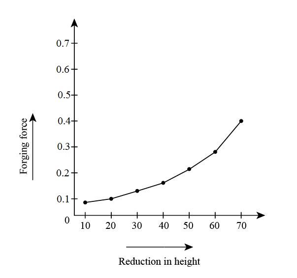
Figure (1)
The force vs. reduction in height curve in open die forging of cylinder.
Answer to Problem 6.74P
The force vs. reduction in height curve in open die forging of cylinder.
Explanation of Solution
Calculation:
Refer to table 2.2 “Typical values of strength coefficient
The flow stress can be calculated as,
The true strain can be calculated as,
Obtain the expression by substituting equation 2 in 1,
The final radius can be calculated as,
The average pressure can be calculated as,
The forging force can be calculated as,
For
The final height for
The final radius can be calculated by substituting the values in equation 4,
The forging force can be calculated at
For
The final height for
The final radius can be calculated by substituting the values in equation 4,
The forging force can be calculated at
For
The final height for
The final radius can be calculated by substituting the values in equation 4,
The forging force can be calculated at
For
The final height for
The final radius can be calculated by substituting the values in equation 4,
The forging force can be calculated at
For
The final height for
The final radius can be calculated by substituting the values in equation 4,
The forging force can be calculated at
For
The final height for
The final radius can be calculated by substituting the values in equation 4,
The forging force can be calculated at
For
The final height for
The final radius can be calculated by substituting the values in equation 4,
The forging force can be calculated at
The plot between forging force and reduction in height is shown in figure (2) below,
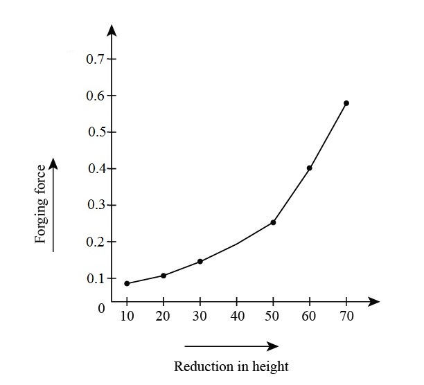
Figure (2)
The force vs. reduction in height curve in open die forging of cylinder.
Explanation of Solution
Calculation:
Refer to table 2.2 “Typical values of strength coefficient
The flow stress can be calculated as,
The true strain can be calculated as,
Obtain the expression by substituting equation 2 in 1,
The final radius can be calculated as,
The average pressure can be calculated as,
The forging force can be calculated as,
For
The final height for
The final radius can be calculated by substituting the values in equation 4,
The forging force can be calculated at
For
The final height for
The final radius can be calculated by substituting the values in equation 4,
The forging force can be calculated at
For
The final height for
The final radius can be calculated by substituting the values in equation 4,
The forging force can be calculated at
For
The final height for
The final radius can be calculated by substituting the values in equation 4,
The forging force can be calculated at
For
The final height for
The final radius can be calculated by substituting the values in equation 4,
The forging force can be calculated at
For
The final height for
The final radius can be calculated by substituting the values in equation 4,
The forging force can be calculated at
For
The final height for
The final radius can be calculated by substituting the values in equation 4,
The forging force can be calculated at
The plot between forging force and reduction in height is shown in figure (3) below,
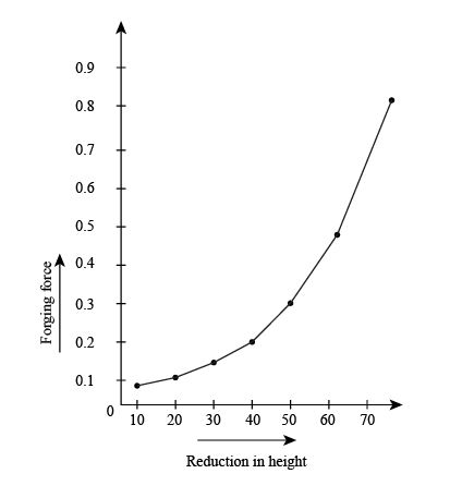
Figure (3)
Want to see more full solutions like this?
Chapter 6 Solutions
EBK MANUFACTURING PROCESSES FOR ENGINEE


- CORRECT AND DETAILED SOLUTION WITH FBD ONLY. I WILL UPVOTE THANK YOU. CORRECT ANSWER IS ALREADY PROVIDED. I REALLY NEED FBD. The roof truss shown carries roof loads, where P = 10 kN. The truss is consisting of circular arcs top andbottom chords with radii R + h and R, respectively.Given: h = 1.2 m, R = 10 m, s = 2 m.Allowable member stresses:Tension = 250 MPaCompression = 180 MPa1. If member KL has square section, determine the minimum dimension (mm).2. If member KL has circular section, determine the minimum diameter (mm).3. If member GH has circular section, determine the minimum diameter (mm).ANSWERS: (1) 31.73 mm; (2) 35.81 mm; (3) 18.49 mmarrow_forwardPROBLEM 3.23 3.23 Under normal operating condi- tions a motor exerts a torque of magnitude TF at F. The shafts are made of a steel for which the allowable shearing stress is 82 MPa and have diameters of dCDE=24 mm and dFGH = 20 mm. Knowing that rp = 165 mm and rg114 mm, deter- mine the largest torque TF which may be exerted at F. TF F rG- rp B CH TE Earrow_forward1. (16%) (a) If a ductile material fails under pure torsion, please explain the failure mode and describe the observed plane of failure. (b) Suppose a prismatic beam is subjected to equal and opposite couples as shown in Fig. 1. Please sketch the deformation and the stress distribution of the cross section. M M Fig. 1 (c) Describe the definition of the neutral axis. (d) Describe the definition of the modular ratio.arrow_forward
- using the theorem of three moments, find all the moments, I only need concise calculations with minimal explanations. The correct answers are provided at the bottomarrow_forwardMechanics of materialsarrow_forwardusing the theorem of three moments, find all the moments, I need concise calculations onlyarrow_forward
- Can you provide steps and an explaination on how the height value to calculate the Pressure at point B is (-5-3.5) and the solution is 86.4kPa.arrow_forwardPROBLEM 3.46 The solid cylindrical rod BC of length L = 600 mm is attached to the rigid lever AB of length a = 380 mm and to the support at C. When a 500 N force P is applied at A, design specifications require that the displacement of A not exceed 25 mm when a 500 N force P is applied at A For the material indicated determine the required diameter of the rod. Aluminium: Tall = 65 MPa, G = 27 GPa. Aarrow_forwardFind the equivalent mass of the rocker arm assembly with respect to the x coordinate. k₁ mi m2 k₁arrow_forward
 Elements Of ElectromagneticsMechanical EngineeringISBN:9780190698614Author:Sadiku, Matthew N. O.Publisher:Oxford University Press
 Mechanics of Materials (10th Edition)Mechanical EngineeringISBN:9780134319650Author:Russell C. HibbelerPublisher:PEARSON
 Thermodynamics: An Engineering ApproachMechanical EngineeringISBN:9781259822674Author:Yunus A. Cengel Dr., Michael A. BolesPublisher:McGraw-Hill Education
 Control Systems EngineeringMechanical EngineeringISBN:9781118170519Author:Norman S. NisePublisher:WILEY
 Mechanics of Materials (MindTap Course List)Mechanical EngineeringISBN:9781337093347Author:Barry J. Goodno, James M. GerePublisher:Cengage Learning
 Engineering Mechanics: StaticsMechanical EngineeringISBN:9781118807330Author:James L. Meriam, L. G. Kraige, J. N. BoltonPublisher:WILEY