
Applied Fluid Mechanics: Global Edition
7th Edition
ISBN: 9781292019611
Author: Robert Mott
Publisher: Pearson Higher Education
expand_more
expand_more
format_list_bulleted
Concept explainers
Videos
Textbook Question
Chapter 6, Problem 6.56PP
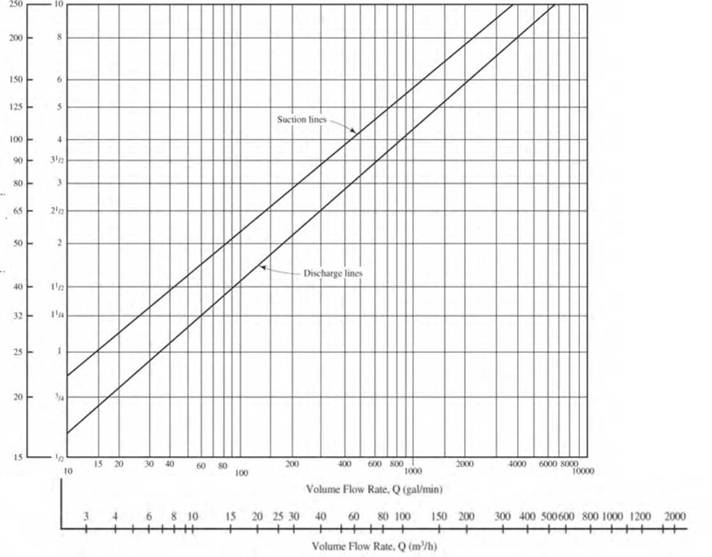
For Problems 6.55-6.57, use Fig. 6.3 to specify suitable Schedule 40 pipe sizes for carrying the given volume flow rate of water in the suction line and in the discharge line of a pumped distribution system. Select the pipe sizes both above and below the curve for the given flow rate| and then calculate the actual velocity of flow in each.
| Suction Line |
Expert Solution & Answer
Want to see the full answer?
Check out a sample textbook solution
Students have asked these similar questions
3. The structure in Figure 3 is loaded by a horizontal force P = 2.4 kN at C. The roller at E is
frictionless. Find the axial force N, the shear force V and the bending moment M at a section
just above the pin B in the member ABC and illustrate their directions on a sketch of the segment
AB.
B
P
D
A
65°
65°
E
all dimensions in meters
Figure 3
4. The distributed load in Figure 4 varies linearly from 3wo per unit length at A to wo per unit
length at B and the beam is built in at A. Find expressions for the shear force V and the bending
moment M as functions of x.
3W0
Wo
A
L
Figure 4
2
B
1. The beam AB in Figure 1 is subjected to a uniformly distributed load wo = 100 N/m. Find
the axial force N, the shear force V and the bending moment M at the point D which is midway
between A and B and illustrate their directions on a sketch of the segment DB.
wo per unit length
A
D'
B
all dimensions in meters
Chapter 6 Solutions
Applied Fluid Mechanics: Global Edition
Ch. 6 - Convert a volume flow rate of 3.0 gal/min to...Ch. 6 - Convert 459 gal/min to rrP/s.Ch. 6 - Convert 3720 gal/min to mJ/sCh. 6 - Convert 34.3 gal/min to mJ/sCh. 6 - Convert a volume flow rate of 125 L/min to m3/s.Ch. 6 - Convert 4500 L/min to m5/s.Ch. 6 - Convert 15 000 L/minto m3/s.Ch. 6 - Convert 459 gal/min to L/mninCh. 6 - Convert 3720 gal/min to L/minCh. 6 - Convert 23.5cm2/stom3/s.
Ch. 6 - '6.11 Convert 0.296cm5/stom3/s.Ch. 6 - Convert 0.105 cm3/s to L/minCh. 6 - Convert 3.53103m3/s to L/min.Ch. 6 - Convert 5.26106m3stoL/min.Ch. 6 - Prob. 6.15PPCh. 6 - Convert 20 gal/min to ft'/s.Ch. 6 - Convert 2500 gal/min to ft5/s.Ch. 6 - Convert 2.50 gal/min to ft3/s.Ch. 6 - Convert 125 ft3/s to gal/minCh. 6 - Convert 0.060 ft3/s to gal/min.Ch. 6 - Convert 0.03 ft5/s to gal/minCh. 6 - Convert ft5/s sto gal/minCh. 6 - Table 6.21 lists the range of typical volume flow...Ch. 6 - Table 6.2 lists the range of typical volume flow...Ch. 6 - A certain deep-well pump for a residence is rated...Ch. 6 - A small pump delivers 0.85 gal/h of liquid...Ch. 6 - A small metering pump delivers 11.4 gal of a water...Ch. 6 - A small metering pump delivers 19.5 mL/min of...Ch. 6 - Water at 10 C is flowing at 0.075 m3/s Calculate...Ch. 6 - Oil for a hydraulic system (sg =0.90 ) is flowing...Ch. 6 - A liquid refrigerant (sg = 1.08) is flowing at a...Ch. 6 - After the refrigerant from Problem 6.31 flashes...Ch. 6 - A fan delivers 640ft3/min (CFM) of air. If the...Ch. 6 - A large blower for a furnace delivers 47000ft3/min...Ch. 6 - A furnace requires 1200 Ib/h of air for efficient...Ch. 6 - If a pump removes 1.65 gal/min of water from a...Ch. 6 - Calculate the diameter of a pipe that would carry...Ch. 6 - If the velocity of a liquid is 1.65 ft/s in a...Ch. 6 - When 2000 L/min of water flows through a circular...Ch. 6 - Water flows at 1.20 m/s in a circular section with...Ch. 6 - Figure 6.16 shows a fabricated assembly made from...Ch. 6 - A standard Schedule 40 steel pipe is to be...Ch. 6 - If water at 180 F is flowing with a velocity of...Ch. 6 - A standard steel tube, 1.5 25-mm OD 3 1,5-mm wall...Ch. 6 - The recommended velocity of flow in the discharge...Ch. 6 - Repeat Problem 6.45, except specify suitable sizes...Ch. 6 - Table 6.2 shows the typical volume flow rate for...Ch. 6 - Repeat Problem 6.47 but use Schedule 80 DM pipeCh. 6 - Compute the resulting velocity of flow if 400...Ch. 6 - Repeat Problem 6.49 for a DN 50 Schedule 30 pipe.Ch. 6 - Compute the resulting velocity of flow if 400...Ch. 6 - Repeat Problem 6.51 for a 4-in Schedule 30 pipe.Ch. 6 - From the list of standard hydraulic steel tubing...Ch. 6 - A standard 6-in Schedule 40 steel pipe is carrying...Ch. 6 - For Problems 6.55-6.57, use Fig. 6.3 O to specify...Ch. 6 - For Problems 6.55-6.57, use Fig. 6.3 to specify...Ch. 6 - For Problems 6.55-6.57, use Fig. 6.3 O to specify...Ch. 6 - A venturi meter is a device that uses a...Ch. 6 - A flow nozzle, shown in Fig. 6.18 is used to...Ch. 6 - Gasoline (sg = 0.67) is flowing at 0.11 m3/s in...Ch. 6 - Water at 10 C is flowing from point A to point B...Ch. 6 - Calculate the volume flow rate of water at 5 C...Ch. 6 - Calculate the pressure required in the larger...Ch. 6 - Kerosene with a specific weight of 50.0 lb/ft3 is...Ch. 6 - For the system shown in Fig. 6.23 ; calculate (a)...Ch. 6 - For the system shown in Fig. 6.24ss, calculate (a)...Ch. 6 - For the tank shown in Fig. 6.25lO, calculate the...Ch. 6 - Calculate the pressure of the air in the sealed...Ch. 6 - For the siphon in Fig. 6.26, calculate (a) the...Ch. 6 - For the siphon in Fig. 6.26 , calculate the...Ch. 6 - For the siphon in Fig. 6.26 , assume that the...Ch. 6 - For the siphon shown in Fig. 6.27, calculate (a)...Ch. 6 - For the special fabricated reducer shown in Fig....Ch. 6 - In the fabricated enlargement shown in Fig. 6.29,...Ch. 6 - Figure 6.30 shows a manometer being used to...Ch. 6 - For the venturi meter shown in Fig. 6.30,...Ch. 6 - Oil with a specific weight of 8.64 kN/m3 flows...Ch. 6 - The venturi meter shown in Fig. 6.32 iP carries...Ch. 6 - Oil with a specific gravity of 0.90 is flowing...Ch. 6 - Oil with a specific gravity of 0.90 is flowing...Ch. 6 - Gasoline (sg = 0.67) is flowing at 4.0 ft3/s in...Ch. 6 - Oil with a specific weight of 55.0lb/ft3 flows...Ch. 6 - Draw a plot of elevation head, pressure head,...Ch. 6 - Prob. 6.84PPCh. 6 - Figure 6.36 shows a system in which water flows...Ch. 6 - Figure 6.37 shows a venturi meter with a U-tube...Ch. 6 - For the tank shown in Fig. 6.38, compute the...Ch. 6 - What depth of fluid above the outlet nozzle is...Ch. 6 - Derive Torricelli's theorem for the velocity of...Ch. 6 - Solve Problem 6.88 using the direct application of...Ch. 6 - To what height will the jet of fluid rise for the...Ch. 6 - To what height will the jet of water rise for the...Ch. 6 - What pressure is required above the water in Fig....Ch. 6 - What pressure is required above the water in Fig....Ch. 6 - Compute the time required to empty the tank shown...Ch. 6 - Compute the time required to empty the tank shown...Ch. 6 - Compute the time required to empty the tank shown...Ch. 6 - Compute the time required to empty the tank shown...Ch. 6 - Compute the time required to reduce the depth in...Ch. 6 - Compute the time required to reduce the depth in...Ch. 6 - Compute the time required to reduce the depth in...Ch. 6 - Compute the time required to reduce the depth in...Ch. 6 - Prob. 6.103PPCh. 6 - Repeat Problem 6.101 if the tank is sealed and a...Ch. 6 - Repeat Problem 6.96 if the tank is sealed and a...Ch. 6 - Repeat Problem 6.100 if the tank is sealed and a...Ch. 6 - A village currently carries water by hand from a...Ch. 6 - A "spa tub" is to be designed to replace bath tubs...Ch. 6 - A simple soft drink system relies on pressurized...Ch. 6 - A concept team for a toy company is considering a...Ch. 6 - 6.111 Bernoulli's principle applies to Venturi...Ch. 6 - Prob. 6.112PPCh. 6 - You are to develop a mixing valve for use in a...Ch. 6 - Prob. 6.114PPCh. 6 - You would like to empty the in-ground pool in the...Ch. 6 - Prob. 6.116PPCh. 6 - Create a spreadsheet for computing the values of...Ch. 6 - Prob. 2APCh. 6 - Prob. 3APCh. 6 - Create a spreadsheet for computing, using Eq....Ch. 6 - Prob. 5APCh. 6 - Create a spreadsheet for computing the velocity of...
Knowledge Booster


Learn more about
Need a deep-dive on the concept behind this application? Look no further. Learn more about this topic, mechanical-engineering and related others by exploring similar questions and additional content below.Similar questions
- 5. Find the shear force V and the bending moment M for the beam of Figure 5 as functions of the distance x from A. Hence find the location and magnitude of the maximum bending moment. w(x) = wox L x L Figure 5 Barrow_forwardDry atmospheric air enters an adiabatic compressor at a 20°C, 1 atm and a mass flow rate of 0.3kg/s. The air is compressed to 1 MPa. The exhaust temperature of the air is 70 degrees hottercompared to the exhaust of an isentropic compression.Determine,a. The exhaust temperature of the air (°C)b. The volumetric flow rate (L/s) at the inlet and exhaust of the compressorc. The power required to accomplish the compression (kW)d. The isentropic efficiency of the compressore. An accounting of the exergy entering the compressor (complete Table P3.9) assuming that thedead state is the same as State 1 (dry atmospheric air)f. The exergetic efficiency of the compressorarrow_forwardA heat pump is operating between a low temperature reservoir of 270 K and a high temperaturereservoir of 340 K. The heat pump receives heat at 255 K from the low temperature reservoir andrejects heat at 355 K to the high temperature reservoir. The heating coefficient of performance ofthe heat pump is 3.2. The heat transfer rate from the low temperature reservoir is 30 kW. The deadstate temperature is 270 K. Determine,a. Power input to the heat pump (kW)b. Heat transfer rate to the high-temperature reservoir (kW)c. Exergy destruction rate associated with the low temperature heat transfer (kW)d. Exergy destruction rate of the heat pump (kW)e. Exergy destruction rate associated with the high temperature heat transfer (kW)f. Exergetic efficiency of the heat pump itselfarrow_forward
- Refrigerant 134a (Table B6, p514 of textbook) enters a tube in the evaporator of a refrigerationsystem at 132.73 kPa and a quality of 0.15 at a velocity of 0.5 m/s. The R134a exits the tube as asaturated vapor at −21°C. The tube has an inside diameter of 3.88 cm. Determine the following,a. The pressure drop of the R134a as it flows through the tube (kPa)b. The volumetric flow rate at the inlet of the tube (L/s)c. The mass flow rate of the refrigerant through the tube (g/s)d. The volumetric flow rate at the exit of the tube (L/s)e. The velocity of the refrigerant at the exit of the tube (m/s)f. The heat transfer rate to the refrigerant (kW) as it flows through the tubearrow_forwardWater enters the rigid, covered tank shown in Figure P3.2 with a volumetric flow rate of 0.32L/s. The water line has an inside diameter of 6.3 cm. The air vent on the tank has an inside diameterof 4.5 cm. The water is at a temperature of 30°C and the air in the tank is at atmospheric pressure(1 atm) and 30°C. Determine the air velocity leaving the vent at the instant shown in the figurearrow_forwardUsing method of sections, determine the force in member BC, HC, and HG. State if these members are in tension or compression. 2 kN A 5 kN 4 kN 4 kN 3 kN H B C D E 3 m F 2 m -5 m 5 m- G 5 m 5 m-arrow_forward
- Determine the normal stresses σn and σt and the shear stress τnt at this point if they act on the rotated stress element shownarrow_forwardUsing method of joints, determine the force in each member of the truss and state if the members are in tension or compression. A E 6 m D 600 N 4 m B 4 m 900 Narrow_forwardQuestion 5. The diagram below shows a mass suspended from a tie supported by two horizontal braces of equal length. The tie forms an angle "a" of 60° to the horizontal plane, the braces form an angle 0 of 50° to the vertical plane. If the mass suspended is 10 tonnes, and the braces are 10m long, find: a) the force in the tie; & b) the force in the braces Horizontal Braces, Tie Massarrow_forward
- = MMB 241 Tutorial 2.pdf 1 / 3 75% + + Tutorial z Topic: Kinematics of Particles:-. QUESTIONS 1. Use the chain-rule and find y and ŷ in terms of x, x and x if a) y=4x² b) y=3e c) y = 6 sin x 2. The particle travels from A to B. Identify the three unknowns, and write the three equations needed to solve for them. 8 m 10 m/s 30° B x 3. The particle travels from A to B. Identify the three unknowns, and write the three equations needed to solve for them. A 40 m/s 20 m B 1arrow_forward3 m³/s- 1 md 45° V 1.8 mr 2mrarrow_forward= MMB 241 Tutorial 2.pdf 3/3 75% + + 6. A particle is traveling along the parabolic path y = 0.25 x². If x = 8 m, vx=8 m/s, and ax= 4 m/s² when t = 2 s, determine the magnitude of the particle's velocity and acceleration at this instant. y = 0.25x² -x 7. Determine the speed at which the basketball at A must be thrown at the angle of 30° so that it makes it to the basket at B. 30° -x 1.5 m B 3 m -10 m- 8. The basketball passed through the hoop even though it barely cleared the hands of the player B who attempted to block it. Neglecting the size of the ball, determine the 2arrow_forward
arrow_back_ios
SEE MORE QUESTIONS
arrow_forward_ios
Recommended textbooks for you
 Elements Of ElectromagneticsMechanical EngineeringISBN:9780190698614Author:Sadiku, Matthew N. O.Publisher:Oxford University Press
 Mechanics of Materials (10th Edition)Mechanical EngineeringISBN:9780134319650Author:Russell C. HibbelerPublisher:PEARSON
 Thermodynamics: An Engineering ApproachMechanical EngineeringISBN:9781259822674Author:Yunus A. Cengel Dr., Michael A. BolesPublisher:McGraw-Hill Education
 Control Systems EngineeringMechanical EngineeringISBN:9781118170519Author:Norman S. NisePublisher:WILEY
 Mechanics of Materials (MindTap Course List)Mechanical EngineeringISBN:9781337093347Author:Barry J. Goodno, James M. GerePublisher:Cengage Learning
 Engineering Mechanics: StaticsMechanical EngineeringISBN:9781118807330Author:James L. Meriam, L. G. Kraige, J. N. BoltonPublisher:WILEY
Elements Of Electromagnetics
Mechanical Engineering
ISBN:9780190698614
Author:Sadiku, Matthew N. O.
Publisher:Oxford University Press
Mechanics of Materials (10th Edition)
Mechanical Engineering
ISBN:9780134319650
Author:Russell C. Hibbeler
Publisher:PEARSON
Thermodynamics: An Engineering Approach
Mechanical Engineering
ISBN:9781259822674
Author:Yunus A. Cengel Dr., Michael A. Boles
Publisher:McGraw-Hill Education
Control Systems Engineering
Mechanical Engineering
ISBN:9781118170519
Author:Norman S. Nise
Publisher:WILEY
Mechanics of Materials (MindTap Course List)
Mechanical Engineering
ISBN:9781337093347
Author:Barry J. Goodno, James M. Gere
Publisher:Cengage Learning
Engineering Mechanics: Statics
Mechanical Engineering
ISBN:9781118807330
Author:James L. Meriam, L. G. Kraige, J. N. Bolton
Publisher:WILEY
Fluid Mechanics - Viscosity and Shear Strain Rate in 9 Minutes!; Author: Less Boring Lectures;https://www.youtube.com/watch?v=_0aaRDAdPTY;License: Standard youtube license