Concept explainers
Videos
Problems 6.19 through 6.22 relate to the comparison of two sinusoidal input signals using a dual-trace oscilloscope. A schematic diagram of the measurement system is shown in Figure 6.40, in which one of the signals is assumed to be a reference standard signal, having a known frequency and amplitude. The oscilloscope trace (Input signal versus Reference signal or X versus Y) for these inputs is called a Lissajous diagram. The problems can also be worked in the laboratory.
Develop the characteristic shape of the Lissajous diagrams for two sinusoidal inputs having the same amplitude, but with the following phase relationships:
- in phase
- ±90 degrees out of phase
- 180 degrees out of phase
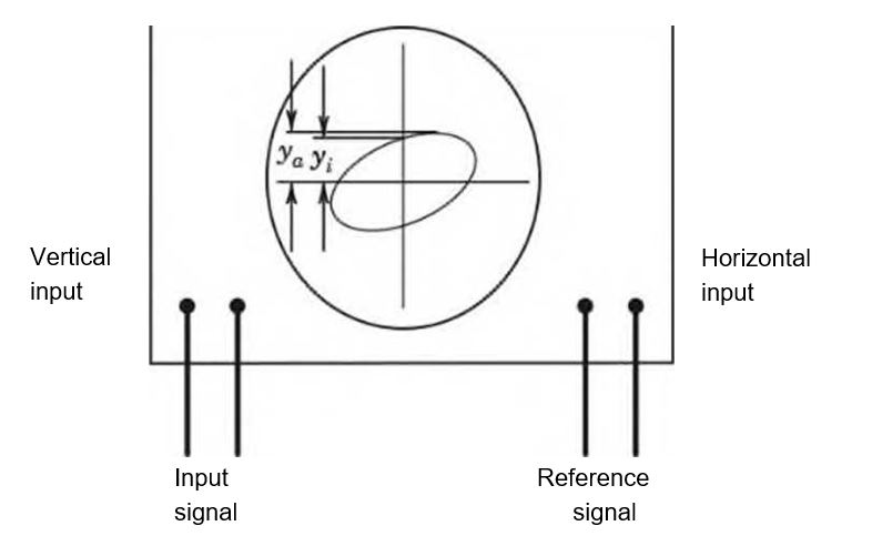
Figure 6.40 Dual-trace oscilloscope for measuring signal characteristics by using Lissajous diagrams.
- Show that the phase angle for two sinusoidal signals can be determined from the relationship sin O = yjya
- Draw a schematic diagram of a measurement system to determine the phase lag resulting from an electronic circuit. Your schematic diagram should include a reference signal, the electronic circuit, and the dual-trace oscilloscope. Discuss the expected result and how a quantitative estimate of the phase lag can be determined.
- Construct Lissajous diagrams for sinusoidal inputs to a dual trace oscilloscope having the following horizontal signal to vertical signal frequency ratios: (a) 1:1, (b) 1:2, (c) 2:1, (d) 1:3, (e) 2:3, (0 5:2. These plots can be easily developed using spreadsheet software and plotting a sufficient number of cycles of each of the input signals.
where the values of y f and yaare illustrated in Figure 6.40 and represent the vertical distance to they intercept and the maximumy value, respectively.
Want to see the full answer?
Check out a sample textbook solution
Chapter 6 Solutions
Theory and Design for Mechanical Measurements


- 1. The beam AB in Figure 1 is subjected to a uniformly distributed load wo = 100 N/m. Find the axial force N, the shear force V and the bending moment M at the point D which is midway between A and B and illustrate their directions on a sketch of the segment DB. wo per unit length A D' B all dimensions in metersarrow_forward5. Find the shear force V and the bending moment M for the beam of Figure 5 as functions of the distance x from A. Hence find the location and magnitude of the maximum bending moment. w(x) = wox L x L Figure 5 Barrow_forwardDry atmospheric air enters an adiabatic compressor at a 20°C, 1 atm and a mass flow rate of 0.3kg/s. The air is compressed to 1 MPa. The exhaust temperature of the air is 70 degrees hottercompared to the exhaust of an isentropic compression.Determine,a. The exhaust temperature of the air (°C)b. The volumetric flow rate (L/s) at the inlet and exhaust of the compressorc. The power required to accomplish the compression (kW)d. The isentropic efficiency of the compressore. An accounting of the exergy entering the compressor (complete Table P3.9) assuming that thedead state is the same as State 1 (dry atmospheric air)f. The exergetic efficiency of the compressorarrow_forward
- A heat pump is operating between a low temperature reservoir of 270 K and a high temperaturereservoir of 340 K. The heat pump receives heat at 255 K from the low temperature reservoir andrejects heat at 355 K to the high temperature reservoir. The heating coefficient of performance ofthe heat pump is 3.2. The heat transfer rate from the low temperature reservoir is 30 kW. The deadstate temperature is 270 K. Determine,a. Power input to the heat pump (kW)b. Heat transfer rate to the high-temperature reservoir (kW)c. Exergy destruction rate associated with the low temperature heat transfer (kW)d. Exergy destruction rate of the heat pump (kW)e. Exergy destruction rate associated with the high temperature heat transfer (kW)f. Exergetic efficiency of the heat pump itselfarrow_forwardRefrigerant 134a (Table B6, p514 of textbook) enters a tube in the evaporator of a refrigerationsystem at 132.73 kPa and a quality of 0.15 at a velocity of 0.5 m/s. The R134a exits the tube as asaturated vapor at −21°C. The tube has an inside diameter of 3.88 cm. Determine the following,a. The pressure drop of the R134a as it flows through the tube (kPa)b. The volumetric flow rate at the inlet of the tube (L/s)c. The mass flow rate of the refrigerant through the tube (g/s)d. The volumetric flow rate at the exit of the tube (L/s)e. The velocity of the refrigerant at the exit of the tube (m/s)f. The heat transfer rate to the refrigerant (kW) as it flows through the tubearrow_forwardWater enters the rigid, covered tank shown in Figure P3.2 with a volumetric flow rate of 0.32L/s. The water line has an inside diameter of 6.3 cm. The air vent on the tank has an inside diameterof 4.5 cm. The water is at a temperature of 30°C and the air in the tank is at atmospheric pressure(1 atm) and 30°C. Determine the air velocity leaving the vent at the instant shown in the figurearrow_forward
- Using method of sections, determine the force in member BC, HC, and HG. State if these members are in tension or compression. 2 kN A 5 kN 4 kN 4 kN 3 kN H B C D E 3 m F 2 m -5 m 5 m- G 5 m 5 m-arrow_forwardDetermine the normal stresses σn and σt and the shear stress τnt at this point if they act on the rotated stress element shownarrow_forwardUsing method of joints, determine the force in each member of the truss and state if the members are in tension or compression. A E 6 m D 600 N 4 m B 4 m 900 Narrow_forward
- Question 5. The diagram below shows a mass suspended from a tie supported by two horizontal braces of equal length. The tie forms an angle "a" of 60° to the horizontal plane, the braces form an angle 0 of 50° to the vertical plane. If the mass suspended is 10 tonnes, and the braces are 10m long, find: a) the force in the tie; & b) the force in the braces Horizontal Braces, Tie Massarrow_forward= MMB 241 Tutorial 2.pdf 1 / 3 75% + + Tutorial z Topic: Kinematics of Particles:-. QUESTIONS 1. Use the chain-rule and find y and ŷ in terms of x, x and x if a) y=4x² b) y=3e c) y = 6 sin x 2. The particle travels from A to B. Identify the three unknowns, and write the three equations needed to solve for them. 8 m 10 m/s 30° B x 3. The particle travels from A to B. Identify the three unknowns, and write the three equations needed to solve for them. A 40 m/s 20 m B 1arrow_forward3 m³/s- 1 md 45° V 1.8 mr 2mrarrow_forward
 Elements Of ElectromagneticsMechanical EngineeringISBN:9780190698614Author:Sadiku, Matthew N. O.Publisher:Oxford University Press
 Mechanics of Materials (10th Edition)Mechanical EngineeringISBN:9780134319650Author:Russell C. HibbelerPublisher:PEARSON
 Thermodynamics: An Engineering ApproachMechanical EngineeringISBN:9781259822674Author:Yunus A. Cengel Dr., Michael A. BolesPublisher:McGraw-Hill Education
 Control Systems EngineeringMechanical EngineeringISBN:9781118170519Author:Norman S. NisePublisher:WILEY
 Mechanics of Materials (MindTap Course List)Mechanical EngineeringISBN:9781337093347Author:Barry J. Goodno, James M. GerePublisher:Cengage Learning
 Engineering Mechanics: StaticsMechanical EngineeringISBN:9781118807330Author:James L. Meriam, L. G. Kraige, J. N. BoltonPublisher:WILEY