Concept explainers
Videos
Using the method of joints, determine the force in each member of the double-pitch roof truss shown. State whether each member is in tension or compression.
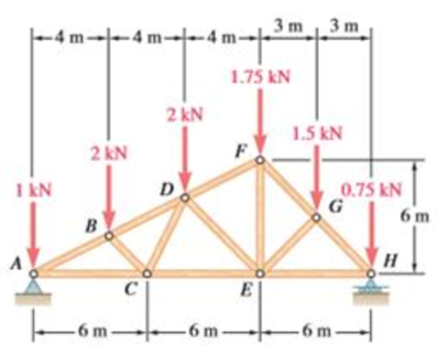
The force in each of the member of the double-pitch roof truss using method of joints and whether each member is in tension or compression.
Answer to Problem 6.165RP
The force in member
Explanation of Solution
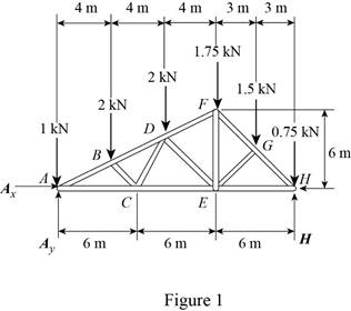
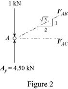
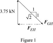
The free-body diagram of the truss is shown in figure 1.
The sum of the moments about the point
Here,
Write the equation for
Here,
Put the above equation in equation (I).
The
Here,
Write the expression for
Here,
Put the above equation in equation (II).
The
Here,
Write the expression for
Put the above equation in equation (III).
Here,
Substitute
The free-body diagram of joint A is shown in figure 2.
The joint A is subject to the forces exerted by
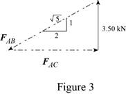
Obtain the magnitudes of the two forces from proportion.
Here,
The free-body diagram of the joint B is shown in figure 4.
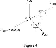
Write the equilibrium equations.
Here,
Write the expression for
Here,
Put the above equation in equation (IV).
The
Here,
Write the expression for
Put the above equation in equation (VI).
Multiply equation (V) by
Subtract equation (VII) from (V).
The free-body diagram of the joint C is shown in figure 5.
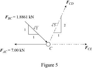
Write the expression for
Here,
Put the above equation in equation (VI).
Write the expression for
Here,
Put the above equation in equation (IV).
The free-body diagram of the joint D is shown in figure 6.
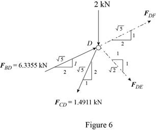
Write the expression for
Here,
Put the above equation in equation (IV).
Write the expression for
Put the above equation in equation (VI).
Add equations (VIII) and (IX).
Subtract equation (IX) from equation (VIII).
Consider the joint F. The free-body diagram of the joint F is shown in figure 7.
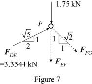
Write the expression for
Here,
Put the above equation in equation (IV).
Write the expression for
Here,
Put the above equation in equation (VI).
Consider the joint G. The free-body diagram of the joint G is shown in figure 8.
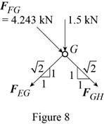
Write the expression for
Here,
Put the above equation in equation (IV).
Write the expression for
Put the above equation in equation (VI).
Add equations (X) and (XI).
Subtract equation (X) from equation (XI).
Consider the joint H. The free-body diagram of the joint H is shown in figure 9.
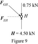
The joint H is subject to the forces exerted by
Obtain the magnitudes of the force from proportion.
Conclusion:
Thus, the force in member
Want to see more full solutions like this?
Chapter 6 Solutions
Loose Leaf for Vector Mechanics for Engineers: Statics and Dynamics


- 1.7 Find the stress distribution in the beam shown in Fig. 1.23 using two beam elements. A. E. I constant M₂ T + FIGURE 1.23 A fixed-pinned beam subjected to a momentarrow_forward42 PART 1 Introduction A. E. I constant FIGURE 1.22 A fixed-pinned beam. 1.6 Find the stress distribution in the beam shown in Fig. 1.22 using two beam elements.arrow_forward1.4 Using a one-beam element idealization, find the stress distribution under a load of P for the uniform cantilever beam shown in Fig. 1.20. A, E, I constant L FIGURE 1.20 A uniform cantilever beamarrow_forward
- Mechanical engineering,FBD required.arrow_forwardSolve this problem and show all of the workarrow_forwardPlease Please use MATLAB with codes and graph. Recreate the following four Figures of the textbook using MATLAB and the appropriate parameters. Comment on your observations for each Figure. List all of the parameters that you have used. The figure is attached below.arrow_forward
- Please only step 6 (last time I asked it was cut off at that point)arrow_forwardPlease Please use a MATLAB with codes and grap. Recreate the following four Figures of the textbook using MATLAB and the appropriate parameters. Comment on your observations for each Figure. List all of the parameters that you have used. The figure attached below.arrow_forwardI REPEAT!!!!! I NEED HANDDRAWING!!!!! NOT A USELESS EXPLANATION!!!! I REPEAT SUBMIT A HANDDRAWING IF YOU CANNOT UNDERSTAND THIS SKIP IT ! I need the real handdrawing complete it by adding these : Pneumatic Valves Each linear actuator must be controlled by a directional control valve (DCV) (e.g., 5/2 or 4/2 valve). The bi-directional motor requires a reversible valve to change rotation direction. Pressure Regulators & Air Supply Include two pressure regulators as per the assignment requirement. Show the main compressed air supply line connecting all components. Limit Switches & Safety Features Attach limit switches to each actuator to detect positions. Implement a two-handed push-button safety system to control actuator movement. Connections Between Components Draw air supply lines linking the compressor, valves, and actuators. Clearly label all inputs and outputs for better understanding.arrow_forward
- I need the real handdrawing complete it by adding these : Pneumatic Valves Each linear actuator must be controlled by a directional control valve (DCV) (e.g., 5/2 or 4/2 valve). The bi-directional motor requires a reversible valve to change rotation direction. Pressure Regulators & Air Supply Include two pressure regulators as per the assignment requirement. Show the main compressed air supply line connecting all components. Limit Switches & Safety Features Attach limit switches to each actuator to detect positions. Implement a two-handed push-button safety system to control actuator movement. Connections Between Components Draw air supply lines linking the compressor, valves, and actuators. Clearly label all inputs and outputs for better understanding.arrow_forwardAn elastic bar of the length L and cross section area A is rigidly attached to the ceiling of a room, and it supports a mass M. Due to the acceleration of gravity g the rod deforms vertically. The deformation of the rod is measured by the vertical displacement u(x) governed by the following equations: dx (σ(x)) + b(x) = 0 PDE σ(x) = Edx du Hooke's law (1) b(x) = gp= body force per unit volume where E is the constant Young's modulus, p is the density, and σ(x) the axial stress in the rod. g * I u(x) L 2arrow_forwardAn elastic bar of the length L and cross section area A is rigidly attached to the ceiling of a room, and it supports a mass M. Due to the acceleration of gravity g the rod deforms vertically. The deformation of the rod is measured by the vertical displacement u(x) governed by the following equations: dx (σ(x)) + b(x) = 0 PDE σ(x) = Edx du Hooke's law (1) b(x) = gp= body force per unit volume where E is the constant Young's modulus, p is the density, and σ(x) the axial stress in the rod. g * I u(x) L 2arrow_forward
 Elements Of ElectromagneticsMechanical EngineeringISBN:9780190698614Author:Sadiku, Matthew N. O.Publisher:Oxford University Press
 Mechanics of Materials (10th Edition)Mechanical EngineeringISBN:9780134319650Author:Russell C. HibbelerPublisher:PEARSON
 Thermodynamics: An Engineering ApproachMechanical EngineeringISBN:9781259822674Author:Yunus A. Cengel Dr., Michael A. BolesPublisher:McGraw-Hill Education
 Control Systems EngineeringMechanical EngineeringISBN:9781118170519Author:Norman S. NisePublisher:WILEY
 Mechanics of Materials (MindTap Course List)Mechanical EngineeringISBN:9781337093347Author:Barry J. Goodno, James M. GerePublisher:Cengage Learning
 Engineering Mechanics: StaticsMechanical EngineeringISBN:9781118807330Author:James L. Meriam, L. G. Kraige, J. N. BoltonPublisher:WILEY