
Videos
The force exerted by each cylinder shown in figure
Answer to Problem 6.158P
The force exerted by the cylinder
Explanation of Solution
Take all
Let P is the force exerted on the bucket at J.
The magnitude of force
The free body diagram of the bucket is sketched below as figure 1.
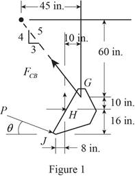
Here,
Write the expression for the moment at
Here,
Above equation implies that net moment at any point is the sum of product of each force acting on the system and perpendicular distance of the force and the point.
The moment at
Thus, the complete expression of net anticlockwise moment
Here,
At equilibrium, the sum of the moment acting at
Write the expression for the total moment acting at
From figure 1 , write the expression for the
From figure 1 , write the expression for the
The free body diagram of the bucket and arm
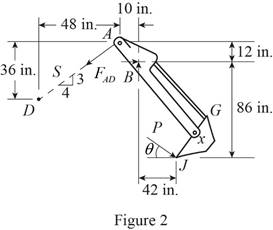
Here,
Write the expression for the moment at
Here,
Above equation implies that net moment at any point is the sum of product of each force acting on the system and perpendicular distance of the force and the point.
The moment at
Thus, the complete expression of net anticlockwise moment
Here,
At equilibrium, the sum of the moment acting at
Write the expression for the total moment acting at
From figure 2 , write the expression for the
Geometry of cylinder
The free body diagram of the bucket and both arms is sketched below as figure 4.
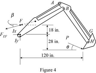
Here,
Write the expression for the moment at
Here,
Above equation implies that net moment at any point is the sum of product of each force acting on the system and perpendicular distance of the force and the point.
The moment at
Thus, the complete expression of net anticlockwise moment
Here,
At equilibrium, the sum of the moment acting at
Write the expression for the total moment acting at
From figure 3 , write the expression for the
Calculation:
Substitute
The negative sign indicate that the cylinder undergoes compression.
Substitute
The negative sign indicate that the cylinder undergoes compression.
Rearrange the equation (X) to get

Substitute
The positive sign indicate that the cylinder
Therefore, the force exerted by the cylinder
Want to see more full solutions like this?
Chapter 6 Solutions
Loose Leaf for Vector Mechanics for Engineers: Statics and Dynamics


- Q2: (15 Marks) A water-LiBr vapor absorption system incorporates a heat exchanger as shown in the figure. The temperatures of the evaporator, the absorber, the condenser, and the generator are 10°C, 25°C, 40°C, and 100°C respectively. The strong liquid leaving the pump is heated to 50°C in the heat exchanger. The refrigerant flow rate through the condenser is 0.12 kg/s. Calculate (i) the heat rejected in the absorber, and (ii) the COP of the cycle. Yo 8 XE-V lo 9 Pc 7 condenser 5 Qgen PG 100 Qabs Pe evaporator PRV 6 PA 10 3 generator heat exchanger 2 pump 185 absorberarrow_forwardQ5:(? Design the duct system of the figure below by using the balanced pressure method. The velocity in the duct attached to the AHU must not exceed 5m/s. The pressure loss for each diffuser is equal to 10Pa. 100CFM 100CFM 100CFM ☑ ☑ 40m AHU -16m- 8m- -12m- 57m 250CFM 40m -14m- 26m 36m ☑ 250CFMarrow_forwardA mass of ideal gas in a closed piston-cylinder system expands from 427 °C and 16 bar following the process law, pv1.36 = Constant (p times v to the power of 1.36 equals to a constant). For the gas, initial : final pressure ratio is 4:1 and the initial gas volume is 0.14 m³. The specific heat of the gas at constant pressure, Cp = 0.987 kJ/kg-K and the specific gas constant, R = 0.267 kJ/kg.K. Determine the change in total internal energy in the gas during the expansion. Enter your numerical answer in the answer box below in KILO JOULES (not in Joules) but do not enter the units. (There is no expected number of decimal points or significant figures).arrow_forward
- my ID# 016948724. Please solve this problem step by steparrow_forwardMy ID# 016948724 please find the forces for Fx=0: fy=0: fz=0: please help me to solve this problem step by steparrow_forwardMy ID# 016948724 please solve the proble step by step find the forces fx=o: fy=0; fz=0; and find shear moment and the bending moment diagran please draw the diagram for the shear and bending momentarrow_forward
- My ID#016948724 please solve this problems and show me every step clear to follow pleasearrow_forwardMy ID# 016948724arrow_forwardPlease do not use any AI tools to solve this question. I need a fully manual, step-by-step solution with clear explanations, as if it were done by a human tutor. No AI-generated responses, please.arrow_forward
 International Edition---engineering Mechanics: St...Mechanical EngineeringISBN:9781305501607Author:Andrew Pytel And Jaan KiusalaasPublisher:CENGAGE L