
Concept explainers
Find the slope
Answer to Problem 34P
The slope
The deflection
The slope
The slope
The deflection
Explanation of Solution
Given information:
The Young’s modulus (E) is 30,000 ksi.
The moment of inertia of the section AB is (I) is
The moment of inertia of the section BD is (I) is
Calculation:
Consider Young’s modulus (E) of the beam is constant.
To draw a
Show the free body diagram of the given beam as in Figure (1).
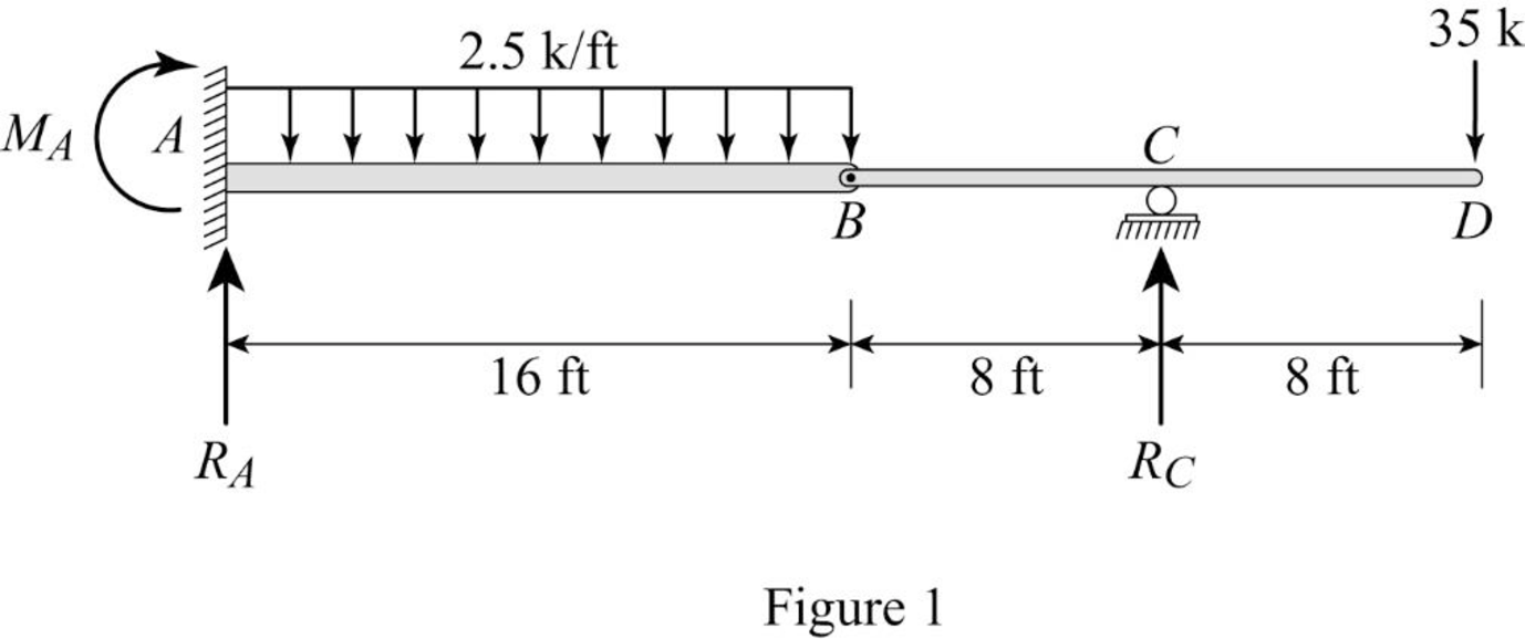
Refer Figure (1),
Consider upward is positive and downward is negative.
Consider clockwise is negative and counterclowise is positive.
Refer Figure (1),
Consider reaction at A and C as
Take moment about point B.
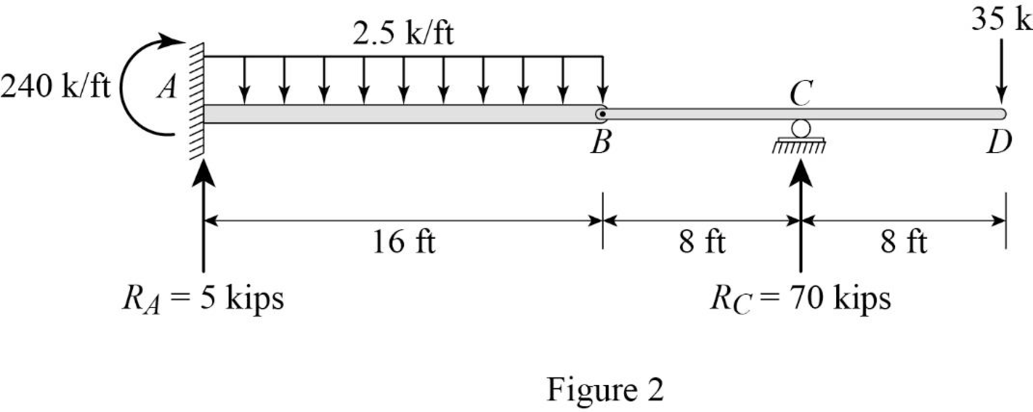
Determine the reaction at C;
Determine the reaction at support A;
Determine the moment at A:
Show the reactions of the given beam as in Figure (2).
Determine the bending moment at B;
Determine the bending moment at C;
Determine the bending moment at D;
Determine the positive bending moment at A;
Show the reaction and point load of the beam as in Figure (3).
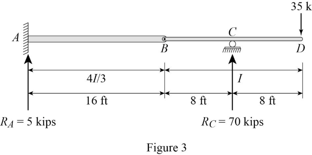
Determine the value of
Substitute
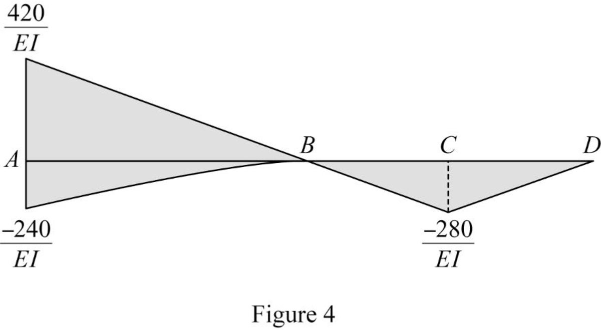
Show the
Show the elastic curve as in Figure (5).
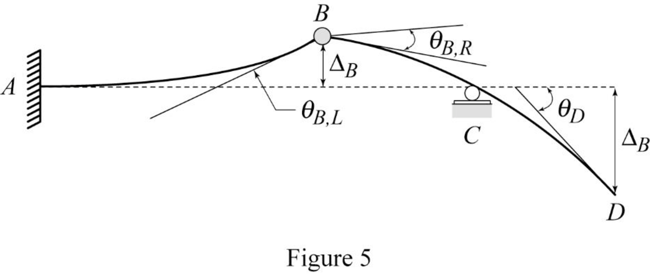
The slope at point B can be calculated by evaluating the change in slope between A and B.
Express the change in slope using the first moment-area theorem as follows:
Here, b is the width and h is the height of the respective triangle and rectangle.
Substitute 16 ft for
Determine the slope B (left) using the relation;
Substitute 30,000 ksi for E and
Hence, the slope at B (left) is
Determine the deflection at B using the relation;
Substitute
Determine the deflection at B (left) using the relation;
Substitute 30,000 ksi for E and
Hence, the deflection at B (left) is
Determine the deflection between B and C using the relation;
Here, b is the width and h is the height of the triangle.
Substitute 8 ft for b and
Express the relationship between the deflection and slope of span BC as follows:
Here,
Substitute
Determine the slope between B and C using the relation;
Substitute 8 ft for b and
Determine the slope at B (right) using the relation;
Substitute
Substitute 30,000 ksi for E and
Hence, the slope at B (right) is
Determine the slope between C and D using the relation;
Here, b is the width and h is the height of the triangle.
Substitute 8 ft for b and
Determine the slope at D using the relation;
Substitute
Substitute 30,000 ksi for E and
Hence, the slope at point D is
Determine the deflection between C and D using the relation;
Substitute
Determine the deflection at point D using the relation;
Substitute 8 ft for
Substitute 30,000 ksi for E and
Hence, the deflection at point D is
Want to see more full solutions like this?
Chapter 6 Solutions
Structural Analysis, SI Edition


- JOB UPDATE QUALCOMM FULL STACK DEVELOPER ASSOCIATE INFOR (FRESHERS) IBM QUALITY ENGINEER DATAVAIL DATABASE ADMINISTRATOR INTOUCH CUST SERVICE (CHAT/EMAIL) ACCENTURE Vinkjobs.com #vinkjobs CUSTOMER SUPPORT Search "Vinkjobs.com" on Googlearrow_forwardHello, I would like to ask if the answer provided in this link is correct based on the floor plan shown in the attached pictures? Kindly verify if the solution matches the actual layout and measurements. Thank you! https://www.bartleby.com/questions-and-answers/i-need-help-estimating-the-required-materials-for-masonry-works-using-chb-in-a-2-storey-residential-/bdb70948-ded3-4461-9057-f63a7a1c5f8farrow_forwardStructural analysis question Cleary explain each step with appropriate solviarrow_forward
- An activity on a non critical path has a total float of 16 days and a duration of 5 days. The start of the activity is delayed by delivery of material for 12 days. A worker shortage makes the activity take 12 days. How far behind the original critical path schedule are you? b.3 days a.0 days d.4 days c.4 days aheadarrow_forwardPlease answer the two questions in detail and as best as you can. Please ensure it is 100% done by human, please do not use AI or chatgpt.arrow_forwardPlease answer the two questions in detail and as best as you can. Please ensure it is 100% done by human, please do not use AI or chatgpt.arrow_forward
- Please answer the two questions in detail and as best as you can. Please ensure it is 100% done by human, please do not use AI or chatgpt.arrow_forwardPlease answer the two questions in detail and as best as you can. Please ensure it is 100% done by human, please do not use AI or chatgpt.arrow_forwardPlease answer the two questions in detail and as best as you can. Please ensure it is 100% done by human, please do not use AI or chatgpt.arrow_forward
- Please provide a handwritten solution to the questionarrow_forwardkevin.w.wickline@wv.govarrow_forwardWhat is the value of the influence line for the bending moment around B at B for the beam shown? Determine the influence line ordinates at 3-m intervals. Select the reaction at support C to be the redundant. A a. 1.875 kN 6 m b. 0.688 kN c. 2.25 kN > d. 0.313 KN B -12 m- El = constant Carrow_forward
