
(a)
Find the expression of the voltage across an inductor
(a)
Answer to Problem 1P
The expression of the voltage across an inductor
Explanation of Solution
Given data:
The current through an inductor is
The inductor value is,
Formula used:
Write the general expression to find the voltage across an inductor as,
Here,
L is the value of inductance of the inductor,
Calculation:
Substitute
Conclusion:
Thus, the expression of the voltage across an inductor
(b)
Calculate the power at the inductor terminals at time of
(b)
Answer to Problem 1P
The power at the inductor terminals at time of
Explanation of Solution
Calculation:
Given that
At time
At time
At time
At time
At time
Calculate the voltage at
Write the formula to find the power in an inductor at
Substitute
PSpice simulation:
Use all the above calculated values to give as an input to the PSpice simulation.
From the given information, the current passing through an inductor and here a small resistor is connected in series with inductor to avoid the simulation error.
Draw the circuit as shown in below Figure 1.
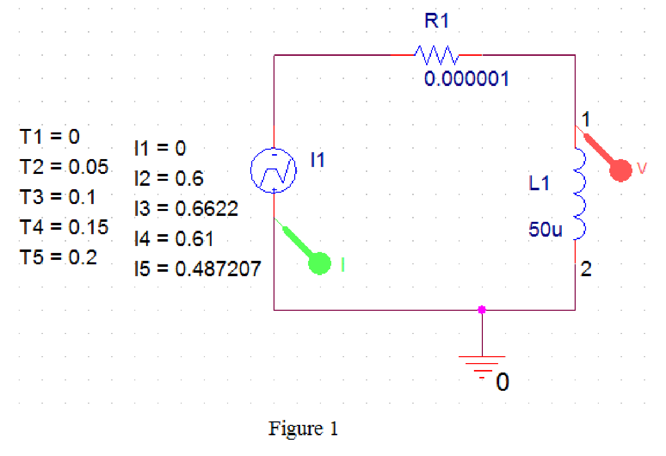
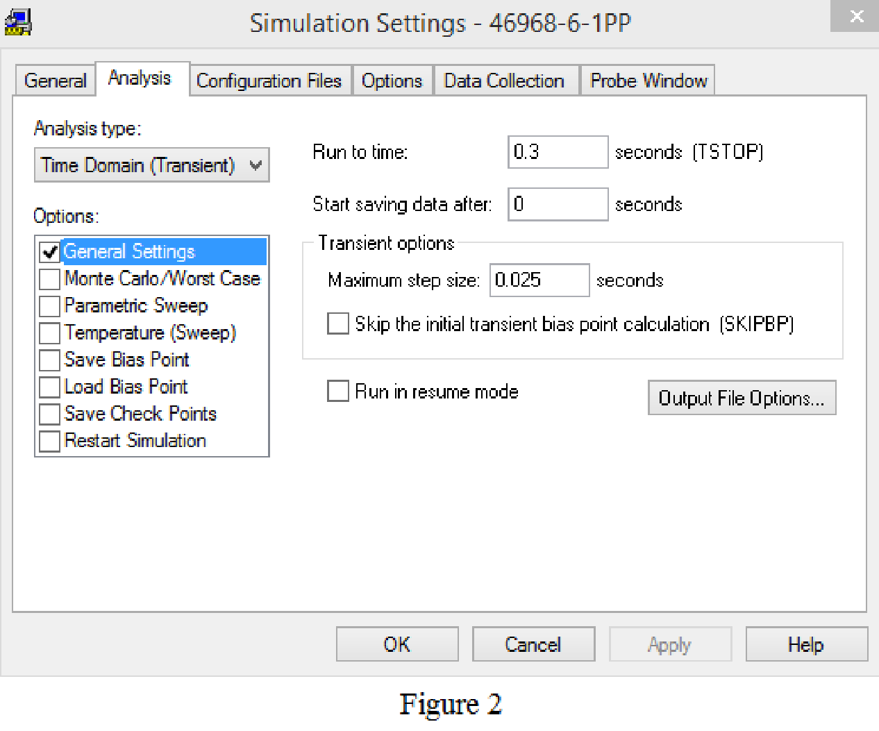
Provide the simulation settings as shown in below Figure 2.
Now, save and run the simulation, then the plot for the input current and voltage across an inductor will be displays as shown in Figure 3.
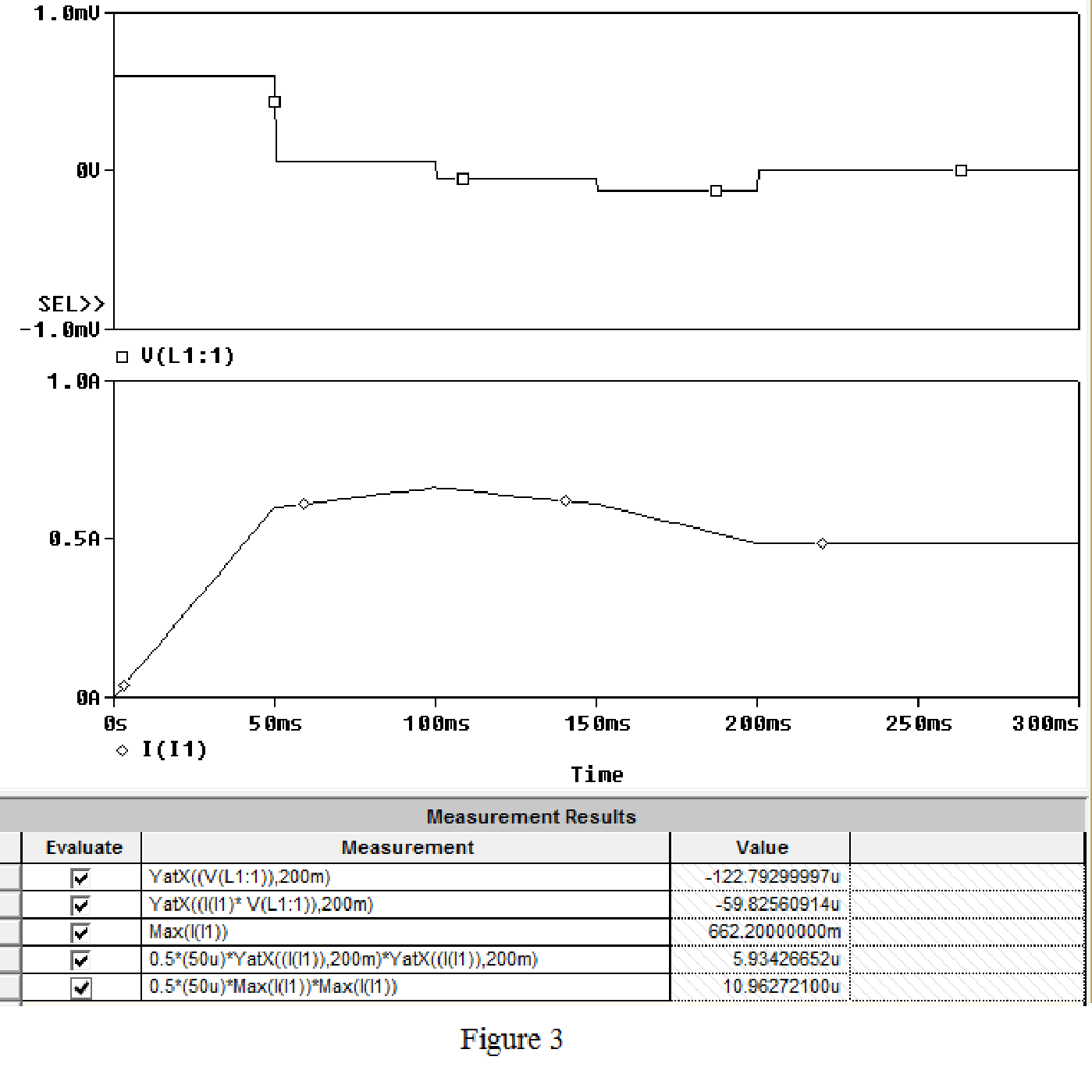
From the Figure 3, the first function is used to read the voltage at
The power calculated at
Conclusion:
Thus, the power at the inductor terminals at time of
(c)
Check whether an inductor is delivering the power or absorbing the power.
(c)
Answer to Problem 1P
An inductor is delivering the power.
Explanation of Solution
Discussion:
The power calculated in an inductor has the negative sign which indicates that the power is delivering by an inductor.
Conclusion:
Thus, an inductor is delivering the power.
(d)
Calculate the energy stored in an inductor in micro joules at
(d)
Answer to Problem 1P
The energy stored in an inductor in at
Explanation of Solution
Discussion:
From the simulation results shown in Part (b), the fourth equation is written to calculate energy stored in an inductor. From the Figure 3, the energy stored in an inductor in at
Conclusion:
Thus, the energy stored in an inductor in at
(e)
Find the maximum energy, and also find the instant of time that occurs.
(e)
Answer to Problem 1P
The maximum energy is
Explanation of Solution
Discussion:
When the current is maximum energy in an inductor also maximum, since the square of current is directly proportional to the energy stored.
From the Figure 3, it is calculated that maximum current as 662.2 mA, that occurs at
Conclusion:
Thus, the maximum energy is
Want to see more full solutions like this?
Chapter 6 Solutions
EBK ELECTRIC CIRCUITS

- Help with homework, with the extra portion part too pleasearrow_forwardRedraw the previous circuit and add a 24 V red lamp to indicate the relay coil is on, a 230 V yellow lamp to indicate the solenoid is on, green lamp to indicate the solenoid is off. Use only one relay, which has multiple contacts.arrow_forwardDesign a control circuit so a 24 V relay , start button, and a stop push button (on/off with memory) operates an electromechanical relay to control a 230 V solenoid Next, Redraw the previous circuit and add a 24 V red lamp to indicate the relay coil is on, a 230 V yellow lamp to indicate the solenoid is on, green lamp to indicate the solenoid is off. Use only one relay, which has multiple contacts.arrow_forward
- please answer it handwritten , thanks! will give thumbs uparrow_forwardEXAMPLE 6.3 Suppose the Fourier transform of a pulse is as follows: (1-a) Ть. 2Ть H(f) = < α (To) (-Tof+ 1 +a (1-a) (1+α) ·<|f|≤· 2 2ть 2Ть (1+α) 0, <\f\ 2Ть where 0≤a≤1. Show that this pulse in both time and frequency domains satisfies the Nyquist criterion.arrow_forwardIn matlabarrow_forward
- not use ai pleasearrow_forwardIn matlabarrow_forwardEXAMPLE 4.4 In a binary symmetric communication (BSC) channel, the input bits transmitted over the channel are either 0 or 1 with probabilities p and 1-p, respectively. Due to channel noise, errors are made. As shown in Figure 4.4, the channel is assumed to be symmetric, which means the probability of receiving 1 when 0 is transmitted is the same as the probability of receiving 0 when 1 is transmit- ted. The conditional probabilities of error are assumed to be each e. Determine the average prob- ability of error, also known as the bit error rate, as well as the a posteriori probabilities.arrow_forward
- What is the bandwidth requirement in Hz for baseband binary transmission at 64 kbps, if the roll-off factor is 0.25?arrow_forwardEXAMPLE 6.4 Suppose the roll-off factor is 25% and the bandwidth of a baseband transmission system satisfying the Nyquist criterion is 30 kHz. Determine the bit rate. Solution 1+α 1arrow_forwardEXAMPLE 4.9 In a communication system, the noise level is modeled as a Gaussian random variable with m=0 and ² = 0.0001. Determine P(X > 0.01) and P(-0.04 ≤x≤ 0.05). 3arrow_forward
 Introductory Circuit Analysis (13th Edition)Electrical EngineeringISBN:9780133923605Author:Robert L. BoylestadPublisher:PEARSON
 Delmar's Standard Textbook Of ElectricityElectrical EngineeringISBN:9781337900348Author:Stephen L. HermanPublisher:Cengage Learning
 Programmable Logic ControllersElectrical EngineeringISBN:9780073373843Author:Frank D. PetruzellaPublisher:McGraw-Hill Education
 Fundamentals of Electric CircuitsElectrical EngineeringISBN:9780078028229Author:Charles K Alexander, Matthew SadikuPublisher:McGraw-Hill Education
 Electric Circuits. (11th Edition)Electrical EngineeringISBN:9780134746968Author:James W. Nilsson, Susan RiedelPublisher:PEARSON
 Engineering ElectromagneticsElectrical EngineeringISBN:9780078028151Author:Hayt, William H. (william Hart), Jr, BUCK, John A.Publisher:Mcgraw-hill Education,