
Concept explainers
Videos
Plot the following graphs for the pressure varies from
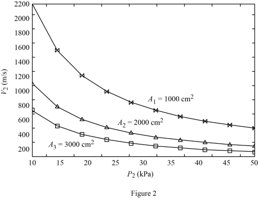
- Exit velocity versus exit pressure power output of turbine
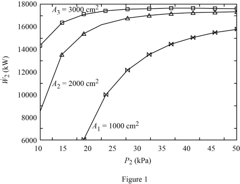
- Turbine power output versus exit pressure power output of turbine
Explanation of Solution
The turbine operates steadily. Hence, the inlet and exit mass flow rates are equal.
Write the formula for inlet mass flow rate.
Here, the cross-sectional area is
At inlet:
The steam is at the state of superheated condition.
Refer Table A-6, “Superheated water”.
Obtain the inlet enthalpy
The turbine operates steadily. Hence, the inlet and exit mass flow rates are equal.
Write the formula for exit mass flow rate.
Here, the cross-sectional area is
Rearrange the Equation (II) to obtain exit velocity
At exit:
Consider the exit pressure
The steam is with the quality of
Write the formula for exit enthalpy
Write the formula for exit specific volume
Here, the enthalpy is
Refer Table A-5, “Saturated water—Pressure table”.
Obtain the following corresponding to the pressure of
Consider the steam flows at steady state. Hence, the inlet and exit mass flow rates are equal.
Write the energy rate balance equation for one inlet and one outlet system.
Here, the rate of heat transfer is
The steam flows at steady state through the turbine. Hence, the rate of change in net energy of the system becomes zero.
Heat loss occurs at the rate of
The Equations (VI) reduced as follows to obtain the work output
Here,
Rewrite the Equation (VII) as follows.
Calculation:
Substitute
Substitute
Equation (V).
Substitute
Consider the exit area
Substitute
Equation (III).
Substitute
The exit velocity
Using excel spread sheet, the exit velocity
| S.No. | |||
| 1 | 10 | 2253.540216 | –22171.1196 |
| 2 | 15 | 1539.230498 | –514.857057 |
| 3 | 20 | 1174.871104 | 7295.806083 |
| 4 | 25 | 952.9435377 | 10965.91684 |
| 5 | 30 | 803.2150134 | 12968.62817 |
| 6 | 40 | 613.4390747 | 14943.44488 |
| 7 | 50 | 497.7670121 | 15822.49054 |
Table 1
Similarly, the exit velocity
| S.No. | |||
| 1 | 10 | 1126.770108 | 8623.292217 |
| 2 | 15 | 769.6152491 | 13851.56455 |
| 3 | 20 | 587.435552 | 15665.73428 |
| 4 | 25 | 476.4717689 | 16472.41662 |
| 5 | 30 | 401.6075067 | 16880.6829 |
| 6 | 40 | 306.7195374 | 17225.27947 |
| 7 | 50 | 248.883506 | 17324.918 |
Table 2
Similarly, the exit velocity
| S.No. | |||
| 1 | 10 | 751.180072 | 14325.96107 |
| 2 | 15 | 513.0768327 | 16512.01299 |
| 3 | 20 | 391.6237013 | 17215.72099 |
| 4 | 25 | 317.6478459 | 17492.1388 |
| 5 | 30 | 267.7383378 | 17605.13749 |
| 6 | 40 | 204.4796916 | 17647.84143 |
| 7 | 50 | 165.9223374 | 17603.1453 |
Table 3
Refer Table 1, 2, and 3.
Plot the graph for the exit pressure
Refer Table 1, 2, and 3.
Plot the graph for the exit pressure
Want to see more full solutions like this?
Chapter 6 Solutions
EBK FUNDAMENTALS OF THERMAL-FLUID SCIEN


- MY ID#016948724 please solve the problem step by spetarrow_forward1 8 4 For the table with 4×4 rows and columns as shown Add numbers so that the sum of any row or column equals .30 Use only these numbers: .1.2.3.4.5.6.10.11.12.12.13.14.14arrow_forwardMY ID# 016948724 please solve this problem step by steparrow_forward
- The pickup truck weighs 3220 Ib and reaches a speed of 30 mi/hr from rest in a distance of 200 ft up the 10-percent incline with constant acceleration. Calculate the normal force under each pair of wheels and the friction force under the rear driving wheels. The effective coefficient of friction between the tires and the road is known to be at least 0.8.arrow_forward1. The figure shows a car jack to support 400kg (W=400kg). In the drawing, the angle (0) varies between 15 and 70 °. The links are machined from AISI 1020 hot-rolled steel bars with a minimum yield strength of 380MPa. Each link consists of two bars, one on each side of the central bearings. The bars are 300mm in length (/) and 25 mm in width (w). The pinned ends have the buckling constant (C) of 1.4 for out of plane buckling. The design factor (nd) is 2.5. (1) Find the thickness (t) of the bars and the factor of safety (n). (2) Check if the bar is an Euler beam. Darrow_forward(Read image)arrow_forward
- UNIVERSIDAD NACIONAL DE SAN ANTONIO ABAD DEL CUSCO PRIMER EXAMEN PARCIAL DE MECÁNICA DE FLUIDOS I ............ Cusco, 23 de setiembre de 2024 AP. Y NOMBRES: ........ 1.- Para el tanque de la figura: a) Calcule la profundidad de la hidrolina si la profundidad del agua es de 2.8 m y el medidor del fondo del tanque da una lectura de 52.3kPa. b) Calcule la profundidad del agua si la profundidad de la hidrolina es 6.90 m y el medidor de la parte inferior del tanque registra una lectura de 125.3 kPa. Hidrolina Sp=0.90 Abertura Agua sup suge to but amulor quit y 2.- Calcule la magnitud de la fuerza resultante sobre el área A-B y la ubicación del centro de presión. Señale la fuerza resultante sobre el área y dimensione su ubicación con claridad. 3.5 ft 12 in: Oil (38-0.93) 14 in 8 inarrow_forwardplease solve this problem and give me the correct answer step by steparrow_forwardplease solve this problem step by step and show the best way that can be explainedarrow_forward
 Elements Of ElectromagneticsMechanical EngineeringISBN:9780190698614Author:Sadiku, Matthew N. O.Publisher:Oxford University Press
 Mechanics of Materials (10th Edition)Mechanical EngineeringISBN:9780134319650Author:Russell C. HibbelerPublisher:PEARSON
 Thermodynamics: An Engineering ApproachMechanical EngineeringISBN:9781259822674Author:Yunus A. Cengel Dr., Michael A. BolesPublisher:McGraw-Hill Education
 Control Systems EngineeringMechanical EngineeringISBN:9781118170519Author:Norman S. NisePublisher:WILEY
 Mechanics of Materials (MindTap Course List)Mechanical EngineeringISBN:9781337093347Author:Barry J. Goodno, James M. GerePublisher:Cengage Learning
 Engineering Mechanics: StaticsMechanical EngineeringISBN:9781118807330Author:James L. Meriam, L. G. Kraige, J. N. BoltonPublisher:WILEY