
MECHANICS OF MATERIALS (LOOSE)-W/ACCESS
10th Edition
ISBN: 9780134583228
Author: HIBBELER
Publisher: PEARSON
expand_more
expand_more
format_list_bulleted
Concept explainers
Videos
Textbook Question
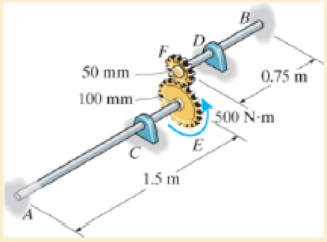
Chapter 5.5, Problem 5.87P
Each has a diameter of 25 mm and they are connected using the gears fixed to their ends. Their other ends are attached to fixed supports at A and B. They are also supported by journal bearings at C and D, which allow free rotation of the shafts along their axes. If a torque of 500 N · m is applied to the gear at E, determine the rotation of this gear.
Expert Solution & Answer

Trending nowThis is a popular solution!

Students have asked these similar questions
A torque of magnitude T = 12 kNm is applied to the end of a tank containing compressed air
under a pressure of 8 MPa (Figure Q1). The tank has a 180 mm inner diameter and a 12 mm
wall thickness. As a result of several tensile tests, it has been found that tensile yeild strength
is σy = 250 MPa for thr grade of steel used. Determine the factor of safety with respect to yeild,
using:
(a) The maximum shearing stress theory
(b) The maximum distortion energy theory
T
Figure Q1
An external pressure of 12 MPa is applied to a closed-end thick cylinder of internal diameter
150 mm and external diameter 300 mm. If the maximum hoop stress on the inner surface of the
cylinder is limited to 30 MPa:
(a) What maximum internal pressure can be applied to the cylinder?
(b) Sketch the variation of hoop and radial stresses across the cylinder wall.
(c) What will be the change in the outside diameter when the above pressure is applied?
[Take E = 207 GPa and v = 0.29]
so
A
4
I need a detailed drawing with explanation
し
i need drawing in solution
motion is as follows;
1- Dwell 45°.
Plot the displacement diagram for a cam with flat follower of width 14 mm. The required
2- Rising 60 mm in 90° with Simple Harmonic Motion.
3- Dwell 90°.
4- Falling 60 mm for 90° with Simple Harmonic Motion.
5- Dwell 45°.
cam is 50 mm.
Then design the cam profile to give the above displacement diagram if the minimum circle diameter of the
か
---2-125
750 x2.01
98P
Chapter 5 Solutions
MECHANICS OF MATERIALS (LOOSE)-W/ACCESS
Ch. 5.3 - Determine the internal torque at each section and...Ch. 5.3 - Determine the. internal torque at each section and...Ch. 5.3 - The solid and hollow shafts are each subjected to...Ch. 5.3 - The motor delivers 10 hp to the shaft. If it...Ch. 5.3 - The solid circular shaft is subjected to an...Ch. 5.3 - The hollow circular shaft is subjected to an...Ch. 5.3 - The shaft is hollow from A to B and solid from B...Ch. 5.3 - Determine the maximum shear stress in the...Ch. 5.3 - Determine the maximum shear stress in the shaft at...Ch. 5.3 - Determine the shear stress a: point A on the...
Ch. 5.3 - The solid 50-mm-diameter shaft is subjected to the...Ch. 5.3 - The gear motor can develop 3 hp when it turns at...Ch. 5.3 - The solid shaft of radius r is subjected to a...Ch. 5.3 - The solid shaft of radius r is subjected to a...Ch. 5.3 - A shaft is made of an aluminum alloy having an...Ch. 5.3 - The copper pipe has an outer diameter of 40 mm and...Ch. 5.3 - The copper pipe has an outer diameter of 2.50 in....Ch. 5.3 - The solid aluminum shaft has a diameter of 50 mm...Ch. 5.3 - The solid aluminum shaft has a diameter of 50 mm....Ch. 5.3 - The solid 30-mm-diameter shaft is used to transmit...Ch. 5.3 - The solid shaft is fixed to the support at C and...Ch. 5.3 - The link acts as part of the elevator control for...Ch. 5.3 - The assembly consists of two sections of...Ch. 5.3 - The shaft has an outer diameter of 100 mm and an...Ch. 5.3 - The shaft has an outer diameter of 100 mm and an...Ch. 5.3 - A steel tube having an outer diameter of 2.5 in....Ch. 5.3 - If the gears are subjected to the torques shown,...Ch. 5.3 - If the gears are subjected to the torques shown,...Ch. 5.3 - The rod has a diameter of 1 in. and a weight of 10...Ch. 5.3 - The rod has a diameter of 1 in. and a weight of 15...Ch. 5.3 - The copper pipe has an outer diameter of 3 in. and...Ch. 5.3 - The copper pipe has an outer diameter of 3 in. and...Ch. 5.3 - The 60-mm-diameter solid shaft is subjected to the...Ch. 5.3 - The 60-mm-diameter solid shaft is subjected to the...Ch. 5.3 - The solid shaft is subjected to the distributed...Ch. 5.3 - The 60-mm-diameter solid shaft is subjected to the...Ch. 5.3 - The solid shaft is subjected to the distributed...Ch. 5.3 - The pipe has an outer radius r0 and inner radius...Ch. 5.3 - The drive shaft AB of an automobile is made of a...Ch. 5.3 - The drive shaft AB of an automobile is to be...Ch. 5.3 - Prob. 5.29PCh. 5.3 - The motor delivers 50 hp while turning at a...Ch. 5.3 - The solid steel shaft AC has a diameter of 25 mm...Ch. 5.3 - The pump operates using the motor that has a power...Ch. 5.3 - The gear motor can develop 110 hp when it turns at...Ch. 5.3 - The gear motor can develop 110 hp when it turns at...Ch. 5.3 - The gear motor can develop 14 hp when it turns at...Ch. 5.3 - The gear motor can develop 2 hp when it turns at...Ch. 5.3 - The 6-hp reducer motor can turn at 1200 rev/min....Ch. 5.3 - The 6-hp reducer motor can turn at 1200 rev/min....Ch. 5.3 - Prob. 5.39PCh. 5.3 - Prob. 5.40PCh. 5.3 - The A-36 steel tubular shaft is 2 m long and has...Ch. 5.3 - Prob. 5.42PCh. 5.3 - The solid shaft has a linear taper from rA at one...Ch. 5.3 - The 1-in.-diameter bent rod is subjected to the...Ch. 5.3 - The 1-in.-diameter bent rod is subjected to the...Ch. 5.3 - A motor delivers 500 hp to the shaft, which is...Ch. 5.4 - The 60 mm-diameter steel shaft is subjected to the...Ch. 5.4 - Prob. 5.10FPCh. 5.4 - The hollow 6061-T6 aluminum shaft has an outer and...Ch. 5.4 - A series of gears are mounted on the...Ch. 5.4 - The 80-mm-diameter shaft is made of steel. If it...Ch. 5.4 - The 80-mm-diameter shaft is made of steel. If it...Ch. 5.4 - The propellers of a ship are connected to an A-36...Ch. 5.4 - Show that the maximum shear strain in the shaft is...Ch. 5.4 - Determine the angle of twist of end B with respect...Ch. 5.4 - Determine the absolute maximum shear stress in the...Ch. 5.4 - Determine the maximum allowable torque T. Also,...Ch. 5.4 - If the allowable shear stress is allow = 80 MPa,...Ch. 5.4 - Determine the angle of twist of the end A.Ch. 5.4 - If gear B supplies 15 kW of power, while gears A,...Ch. 5.4 - If the shaft is made of steel with the allowable...Ch. 5.4 - Prob. 5.56PCh. 5.4 - If the rotation of the 100-mm-diameter A-36 steel...Ch. 5.4 - If the rotation of the 100-mm-diameter A-36 steel...Ch. 5.4 - It has a diameter of 1 in. and is supported by...Ch. 5.4 - Prob. 5.60PCh. 5.4 - Determine the absolute maximum shear stress in the...Ch. 5.4 - If the rotation of the 100-mm-diameter A992 steel...Ch. 5.4 - If the mixer is connected to an A-36 steel tubular...Ch. 5.4 - If the mixer is connected to an A-36 steel tubular...Ch. 5.4 - Also, calculate the absolute maximum shear stress...Ch. 5.4 - When it is rotating at 80 rad/s. it transmits 32...Ch. 5.4 - It is required to transmit 35 kW of power from the...Ch. 5.4 - Determine the angle of twist at end A. The shear...Ch. 5.4 - If a torque of T = 50 N m is applied to the bolt...Ch. 5.4 - If a torque of T= 50N m is applied to the bolt...Ch. 5.4 - If the motor delivers 4 MW of power to the shaft...Ch. 5.4 - Determine the angle of twist at the free end A of...Ch. 5.4 - Prob. 5.73PCh. 5.4 - Prob. 5.74PCh. 5.4 - Determine the angle of twist at the free end A of...Ch. 5.4 - If the shaft is subjected to a torque T at its...Ch. 5.5 - Gst = 75 GPa.Ch. 5.5 - The A992 steel shaft has a diameter of 60 mm and...Ch. 5.5 - If the shaft is fixed at its ends A and B and...Ch. 5.5 - and a thickness of 0.125 in. The coupling on it at...Ch. 5.5 - The coupling on it at C is being tightened using...Ch. 5.5 - The shaft is made of L2 tool steel, has a diameter...Ch. 5.5 - The shaft is made of L2 tool steel, has a diameter...Ch. 5.5 - If the allowable shear stresses for the magnesium...Ch. 5.5 - If a torque of T = 5 kNm is applied to end A,...Ch. 5.5 - Each has a diameter of 25 mm and they are...Ch. 5.5 - Each has a diameter of 25 mm and they are...Ch. 5.5 - It is fixed at its ends and subjected to a torque...Ch. 5.5 - 5–89. Determine the absolute maximum shear stress...Ch. 5.5 - Each has a diameter of 1.5 in. and they are...Ch. 5.5 - The shaft is subjected to a torque of 800 lbft....Ch. 5.5 - The shaft is made of 2014-T6 aluminum alloy and is...Ch. 5.5 - The tapered shaft is confined by the fixed...Ch. 5.5 - Determine the reactions at the fixed supports A...Ch. 5.7 - If the yield stress for brass is Y = 205 MPa,...Ch. 5.7 - By what percentage is the shaft of circular cross...Ch. 5.7 - Prob. 5.97PCh. 5.7 - If it is subjected to the torsional loading,...Ch. 5.7 - Solve Prob.5-98 for the maximum shear stress...Ch. 5.7 - determine the maximum shear stress in the shaft....Ch. 5.7 - If the shaft has an equilateral triangle cross...Ch. 5.7 - by 2 in. square cross section, and it is subjected...Ch. 5.7 - is applied to the tube If the wall thickness is...Ch. 5.7 - If it is 2 m long, determine the maximum shear...Ch. 5.7 - Also, find the angle of twist of end B. The shaft...Ch. 5.7 - Also, find the corresponding angle of twist at end...Ch. 5.7 - If the solid shaft is made from red brass C83400...Ch. 5.7 - If the solid shaft is made from red brass C83400...Ch. 5.7 - The tube is 0.1 in. thick.Ch. 5.7 - Prob. 5.110PCh. 5.7 - Determine the average shear stress in the tube if...Ch. 5.7 - By what percentage is the torsional strength...Ch. 5.7 - Prob. 5.113PCh. 5.7 - Prob. 5.114PCh. 5.7 - If the allowable shear stress is allow = 8 ksi,...Ch. 5.7 - Prob. 5.116PCh. 5.7 - If the allowable shear stress is allow = 80 MPa,...Ch. 5.7 - If the applied torque is T = 50 Nm, determine the...Ch. 5.7 - If it is subjected to a torque of T = 40 Nm....Ch. 5.10 - If the transition between the cross sections has a...Ch. 5.10 - Prob. 5.121PCh. 5.10 - If the radius of the fillet weld connecting the...Ch. 5.10 - Prob. 5.123PCh. 5.10 - Determine the maximum shear stress in the shaft. A...Ch. 5.10 - Prob. 5.125PCh. 5.10 - Determine the radius of the elastic core produced...Ch. 5.10 - Assume that the material becomes fully plastic.Ch. 5.10 - diameter is subjected to a torque of 100 in.kip....Ch. 5.10 - Determine the torque T needed to form an elastic...Ch. 5.10 - Determine the torque applied to the shaft.Ch. 5.10 - Prob. 5.131PCh. 5.10 - Determine the ratio of the plastic torque Tp to...Ch. 5.10 - Determine the applied torque T, which subjects the...Ch. 5.10 - Determine the torque needed to just cause the...Ch. 5.10 - Determine the radius of its elastic core if it is...Ch. 5.10 - Plot the shear-stress distribution acting along a...Ch. 5.10 - If the material obeys a shear stress-strain...Ch. 5.10 - It is made of an elastic perfectly plastic...Ch. 5.10 - Prob. 5.139PCh. 5.10 - Prob. 5.140PCh. 5.10 - is made from an elastic perfectly plastic material...Ch. 5.10 - Prob. 5.142PCh. 5.10 - If the materials have the diagrams shown,...Ch. 5.10 - Determine the torque required to cause a maximum...Ch. 5 - The shaft is made of A992 steel and has an...Ch. 5 - The shaft is made of A992 steel and has an...Ch. 5 - Determine the shear stress at the mean radius p =...Ch. 5 - If the thickness of its 2014-T6-aluminum skin is...Ch. 5 - Determine which shaft geometry will resist the...Ch. 5 - If couple forces P = 3 kip are applied to the...Ch. 5 - If the allowable shear stress for the aluminum is...Ch. 5 - Determine the angle of twist of its end A if it is...Ch. 5 - This motion is caused by the unequal belt tensions...
Additional Engineering Textbook Solutions
Find more solutions based on key concepts
CONCEPT QUESTIONS
15.CQ3 The ball rolls without slipping on the fixed surface as shown. What is the direction ...
Vector Mechanics for Engineers: Statics and Dynamics
Write a summary list of the problem-solving steps identified in the chapter, using your own words.
BASIC BIOMECHANICS
Why is the study of database technology important?
Database Concepts (8th Edition)
Assume a telephone signal travels through a cable at two-thirds the speed of light. How long does it take the s...
Electric Circuits. (11th Edition)
17–1C A high-speed aircraft is cruising in still air. How does the temperature of air at the nose of the aircra...
Thermodynamics: An Engineering Approach
Knowledge Booster


Learn more about
Need a deep-dive on the concept behind this application? Look no further. Learn more about this topic, mechanical-engineering and related others by exploring similar questions and additional content below.Similar questions
- Figure below shows a link mechanism in which the link OA rotates uniformly in an anticlockwise direction at 10 rad/s. the lengths of the various links are OA=75 mm, OB-150 mm, BC=150 mm, CD-300 mm. Determine for the position shown, the sliding velocity of D. A 45 B Space Diagram o NTS (Not-to-Scale) C Darrow_forwardI need a detailed drawing with explanation so Solle 4 يكا Pax Pu + 96** motion is as follows; 1- Dwell 45°. Plot the displacement diagram for a cam with flat follower of width 14 mm. The required 2- Rising 60 mm in 90° with Simple Harmonic Motion. 3- Dwell 90°. 4- Falling 60 mm for 90° with Simple Harmonic Motion. 5- Dwell 45°. cam is 50 mm. Then design the cam profile to give the above displacement diagram if the minimum circle diameter of the 55 ---20125 750 X 2.01 1989arrow_forwardAshaft fitted with a flywheel rotates at 300 rpm. and drives a machine. The torque required to drive the machine varies in a cyclic manner over a period of 2 revolutions. The torque drops from 20,000 Nm to 10,000 Nm uniformly during 90 degrees and remains constant for the following 180 degrees. It then rises uniformly to 35,000 Nm during the next 225 degrees and after that it drops to 20,000 in a uniform manner for 225 degrees, the cycle being repeated thereafter. Determine the power required to drive the machine and percentage fluctuation in speed, if the driving torque applied to the shaft is constant and the mass of the flywheel is 12 tonnes with radius of gyration of 500 mm. What is the maximum angular acceleration of the flywheel. 35,000 TNM 20,000 10,000 0 90 270 495 Crank angle 8 degrees 720arrow_forward
- chanism shown in figure below, the crank OA rotates at 60 RPM counterclockwise. The velocity diagram is also drawn to scale (take dimensions from space diagram). Knowing that QCD is rigid plate, determine: a. Linear acceleration of slider at B, b. Angular acceleration of the links AC, plate CQD, and BD. D Space Diagram Scale 1:10 A ES a o,p,g b Velocity Diagram Scale 50 mm/(m/s) darrow_forwardA thick closed cylinder, 100 mm inner diameter and 200 mm outer diameter is subjected to an internal pressure of 230 MPa and outer pressure of 70 MPa. Modulus of elasticity, E=200 GPa. and Poisson's ratio is 0.3, determine: i) The maximum hoop stress ii) The maximum shear stress iii) The new dimension of the outer diameter due to these inner and outer pressures.arrow_forwardA ә レ shaft fitted with a flywheel rotates at 300 rpm. and drives a machine. The torque required to drive the machine varies in a cyclic manner over a period of 2 revolutions. The torque drops from 20,000 Nm to 10,000 Nm uniformly during 90 degrees and remains constant for the following 180 degrees. It then rises uniformly to 35,000 Nm during the next 225 degrees and after that it drops to 20,000 in a uniform manner for 225 degrees, the cycle being repeated thereafter. Determine the power required to drive the machine and percentage fluctuation in speed, if the driving torque applied to the shaft is constant and the mass of the flywheel is 12 tonnes with radius of gyration of 500 mm. What is the maximum angular acceleration of the flywheel. 35,000 TNm 20,000 10,000 495 Crank angle 8 degrees 270 0 90 か ---20125 750 X 2.01 44 720 sarrow_forward
- The gas tank is made from A-36 steel (σy = 250 MPa) and has an inner diameter of 3.50 m. If the tank is designed to withstand a pressure of 1.2 MPa, determine the required minimum wall thickness to the nearest millimeter using (a) The maximum-shear-stress theory (b) Maximum distortion- energy theory. Apply a factor of safety of 1.5 against yielding.arrow_forwardә レ Figure below shows a link mechanism in which the link OA rotates uniformly in an anticlockwise direction at 10 rad/s. the lengths of the various links are OA=75 mm, OB-150 mm, BC=150 mm, CD-300 mm. Determine for the position shown, the sliding velocity of D. A A B # Space Diagram o NTS (Not-to-Scale) C 10 =--20125 735) 750 x2.01 اهarrow_forward2 レ Tanism in which the link OA mm. O anticlockwise direction at 10 rad/s, the lengths of the various links are OA=75mm, OB=150mm, BC=150mm,CD=300mm. Determine for the position shown, the sliding velocity of D. A A Space Diagram o NT$ (Not-to-Scale) B # C か 750 x2.01 165 79622arrow_forward
- Ashaft fitted with a flywheel rotates at 300 rpm. and drives a machine. The torque required to drive the machine varies in a cyclic manner over a period of 2 revolutions. The torque drops from 20,000 Nm to 10,000 Nm uniformly during 90 degrees and remains constant for the following 180 degrees. It then rises uniformly to 35,000 Nm during the next 225 degrees and after that it drops to 20,000 in a uniform manner for 225 degrees, the cycle being repeated thereafter. Determine the power required to drive the machine and percentage fluctuation in speed, if the driving torque applied to the shaft is constant and the mass of the flywheel is 12 tonnes with radius of gyration of 500 mm. What is the maximum angular acceleration of the flywheel. 35,000 TNM 20,000 10,000 0 90 270 495 Crank angle 8 degrees 720arrow_forwardFigure below shows a link mechanism in which the link OA rotates uniformly in an anticlockwise direction at 10 rad/s. the lengths of the various links are OA=75 mm, OB-150 mm, BC=150 mm, CD-300 mm. Determine for the position shown, the sliding velocity of D. A 45 B Space Diagram o NTS (Not-to-Scale) C Darrow_forwardmotion is as follows; 1- Dwell 45°. Plot the displacement diagram for a cam with flat follower of width 14 mm. The required 2- Rising 60 mm in 90° with Simple Harmonic Motion. 3- Dwell 90°. 4- Falling 60 mm for 90° with Simple Harmonic Motion. 5- Dwell 45°. Then design the cam profile to give the above displacement diagram if the minimum circle diameter of the cam is 50 mm.arrow_forward
arrow_back_ios
SEE MORE QUESTIONS
arrow_forward_ios
Recommended textbooks for you
 International Edition---engineering Mechanics: St...Mechanical EngineeringISBN:9781305501607Author:Andrew Pytel And Jaan KiusalaasPublisher:CENGAGE L
International Edition---engineering Mechanics: St...
Mechanical Engineering
ISBN:9781305501607
Author:Andrew Pytel And Jaan Kiusalaas
Publisher:CENGAGE L
Power Transmission; Author: Terry Brown Mechanical Engineering;https://www.youtube.com/watch?v=YVm4LNVp1vA;License: Standard Youtube License