
Mechanics of Materials (10th Edition)
10th Edition
ISBN: 9780134319650
Author: Russell C. Hibbeler
Publisher: PEARSON
expand_more
expand_more
format_list_bulleted
Concept explainers
Videos
Textbook Question
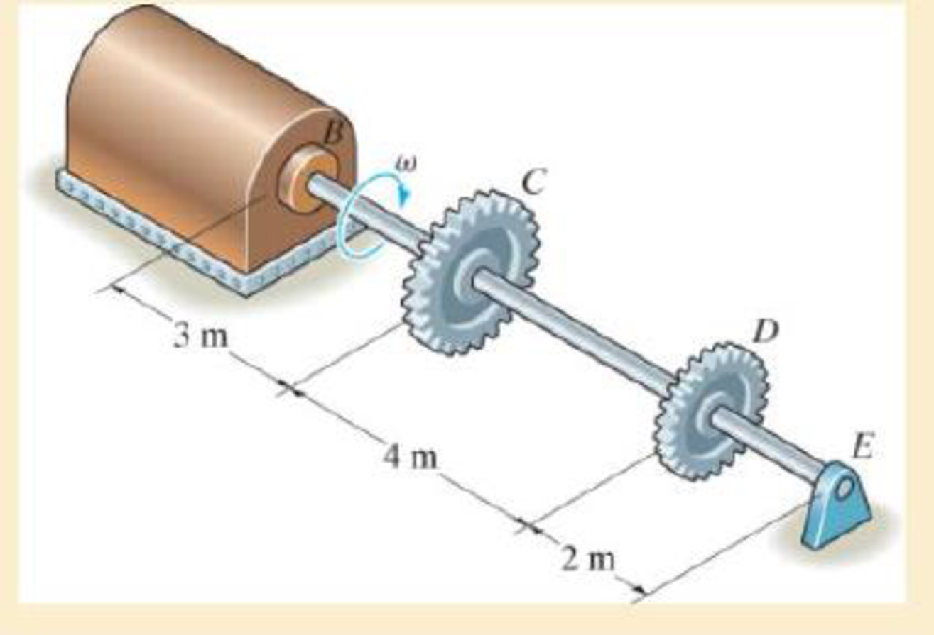
Chapter 5.4, Problem 5.57P
If the rotation of the 100-mm-diameter A-36 steel shaft is ω = 800 rev/min., determine the absolute maximum shear stress in the shaft and the angle of twist of end E of the shaft relative to B. The journal bearing at E allows the shaft to turn freely about its axis.
Expert Solution & Answer

Learn your wayIncludes step-by-step video

schedule09:13
Students have asked these similar questions
Temperature (°C)
100
4. Consider the solidification of a binary Pb-10%Sn alloy. Assume that during solidification,
there is complete mixing in the liquid and no diffusion in the solid. Use the phase diagram
below to answer the following question.
(a)
Draw (on the phase diagram) the compositions of the liquid and the solid at the
interface as a function of temperature during solidification.
(b) Illustrate on the phase diagram how one would calculate the volume fraction solidified
at a given temperature.
(c)
(d)
Indicate the temperature at which solidification is complete.
Do you expect ẞ to be present in the as-cast microstructure? Explain
300
327°C
200
a
(Pb)
20
20
a + L
18.3
183°C
α + β
40
60
Composition (wt% Sn)
Liquid
600
500
232°C
B+L
400
B
61.9
97.8
300
808
100
(Sn)
200
100
Temperature (°F)
I tried this problem a couple of times and don't know where I'm going wrong can you help me out please
y(0)=1,
Using Laplace transforms solve the following differential
equations :
11) y"-4y+4y=0,
12) y+2y+2y=0,
y(0)=2.1,
y'(0) = 3.9
y'(0)=-3.
13) y+7y+12y=21e",
y(0)=3.5,
y'(0)=-10.
14) +9y=10e.
y(0)=0,
y'(0) = 0.
15) y+3y+2.25y=91³ +64,
y(0)=1,
y'(0) = 31.5
16) -6y+5y= 29 cos(21),
y(0)=3.2,
y'(0)=6.2
17) "+2y+2y=0,
y(0)=0,
y'(0)=1.
18) +2y+17y=0,
y(0)=0,
y'(0)=12.
19) y-4y+5y=0,
y(0)=1,
y'(0) = 2.
20) 9y-6y+y=0,
y(0)=3,
y'(0)=1.
21) -2y+10y=0,
y(0)=3,
y'(0)=3.
Chapter 5 Solutions
Mechanics of Materials (10th Edition)
Ch. 5.3 - Determine the internal torque at each section and...Ch. 5.3 - Determine the. internal torque at each section and...Ch. 5.3 - The solid and hollow shafts are each subjected to...Ch. 5.3 - The motor delivers 10 hp to the shaft. If it...Ch. 5.3 - The solid circular shaft is subjected to an...Ch. 5.3 - The hollow circular shaft is subjected to an...Ch. 5.3 - The shaft is hollow from A to B and solid from B...Ch. 5.3 - Determine the maximum shear stress in the...Ch. 5.3 - Determine the maximum shear stress in the shaft at...Ch. 5.3 - Determine the shear stress a: point A on the...
Ch. 5.3 - The solid 50-mm-diameter shaft is subjected to the...Ch. 5.3 - The gear motor can develop 3 hp when it turns at...Ch. 5.3 - The solid shaft of radius r is subjected to a...Ch. 5.3 - The solid shaft of radius r is subjected to a...Ch. 5.3 - A shaft is made of an aluminum alloy having an...Ch. 5.3 - The copper pipe has an outer diameter of 40 mm and...Ch. 5.3 - The copper pipe has an outer diameter of 2.50 in....Ch. 5.3 - The solid aluminum shaft has a diameter of 50 mm...Ch. 5.3 - The solid aluminum shaft has a diameter of 50 mm....Ch. 5.3 - The solid 30-mm-diameter shaft is used to transmit...Ch. 5.3 - The solid shaft is fixed to the support at C and...Ch. 5.3 - The link acts as part of the elevator control for...Ch. 5.3 - The assembly consists of two sections of...Ch. 5.3 - The shaft has an outer diameter of 100 mm and an...Ch. 5.3 - The shaft has an outer diameter of 100 mm and an...Ch. 5.3 - A steel tube having an outer diameter of 2.5 in....Ch. 5.3 - If the gears are subjected to the torques shown,...Ch. 5.3 - If the gears are subjected to the torques shown,...Ch. 5.3 - The rod has a diameter of 1 in. and a weight of 10...Ch. 5.3 - The rod has a diameter of 1 in. and a weight of 15...Ch. 5.3 - The copper pipe has an outer diameter of 3 in. and...Ch. 5.3 - The copper pipe has an outer diameter of 3 in. and...Ch. 5.3 - The 60-mm-diameter solid shaft is subjected to the...Ch. 5.3 - The 60-mm-diameter solid shaft is subjected to the...Ch. 5.3 - The solid shaft is subjected to the distributed...Ch. 5.3 - The 60-mm-diameter solid shaft is subjected to the...Ch. 5.3 - The solid shaft is subjected to the distributed...Ch. 5.3 - The pipe has an outer radius r0 and inner radius...Ch. 5.3 - The drive shaft AB of an automobile is made of a...Ch. 5.3 - The drive shaft AB of an automobile is to be...Ch. 5.3 - Prob. 5.29PCh. 5.3 - The motor delivers 50 hp while turning at a...Ch. 5.3 - The solid steel shaft AC has a diameter of 25 mm...Ch. 5.3 - The pump operates using the motor that has a power...Ch. 5.3 - The gear motor can develop 110 hp when it turns at...Ch. 5.3 - The gear motor can develop 110 hp when it turns at...Ch. 5.3 - The gear motor can develop 14 hp when it turns at...Ch. 5.3 - The gear motor can develop 2 hp when it turns at...Ch. 5.3 - The 6-hp reducer motor can turn at 1200 rev/min....Ch. 5.3 - The 6-hp reducer motor can turn at 1200 rev/min....Ch. 5.3 - Prob. 5.39PCh. 5.3 - Prob. 5.40PCh. 5.3 - The A-36 steel tubular shaft is 2 m long and has...Ch. 5.3 - Prob. 5.42PCh. 5.3 - The solid shaft has a linear taper from rA at one...Ch. 5.3 - The 1-in.-diameter bent rod is subjected to the...Ch. 5.3 - The 1-in.-diameter bent rod is subjected to the...Ch. 5.3 - A motor delivers 500 hp to the shaft, which is...Ch. 5.4 - The 60 mm-diameter steel shaft is subjected to the...Ch. 5.4 - Prob. 5.10FPCh. 5.4 - The hollow 6061-T6 aluminum shaft has an outer and...Ch. 5.4 - A series of gears are mounted on the...Ch. 5.4 - The 80-mm-diameter shaft is made of steel. If it...Ch. 5.4 - The 80-mm-diameter shaft is made of steel. If it...Ch. 5.4 - The propellers of a ship are connected to an A-36...Ch. 5.4 - Show that the maximum shear strain in the shaft is...Ch. 5.4 - Determine the angle of twist of end B with respect...Ch. 5.4 - Determine the absolute maximum shear stress in the...Ch. 5.4 - Determine the maximum allowable torque T. Also,...Ch. 5.4 - If the allowable shear stress is allow = 80 MPa,...Ch. 5.4 - Determine the angle of twist of the end A.Ch. 5.4 - If gear B supplies 15 kW of power, while gears A,...Ch. 5.4 - If the shaft is made of steel with the allowable...Ch. 5.4 - Prob. 5.56PCh. 5.4 - If the rotation of the 100-mm-diameter A-36 steel...Ch. 5.4 - If the rotation of the 100-mm-diameter A-36 steel...Ch. 5.4 - It has a diameter of 1 in. and is supported by...Ch. 5.4 - Prob. 5.60PCh. 5.4 - Determine the absolute maximum shear stress in the...Ch. 5.4 - If the rotation of the 100-mm-diameter A992 steel...Ch. 5.4 - If the mixer is connected to an A-36 steel tubular...Ch. 5.4 - If the mixer is connected to an A-36 steel tubular...Ch. 5.4 - Also, calculate the absolute maximum shear stress...Ch. 5.4 - When it is rotating at 80 rad/s. it transmits 32...Ch. 5.4 - It is required to transmit 35 kW of power from the...Ch. 5.4 - Determine the angle of twist at end A. The shear...Ch. 5.4 - If a torque of T = 50 N m is applied to the bolt...Ch. 5.4 - If a torque of T= 50N m is applied to the bolt...Ch. 5.4 - If the motor delivers 4 MW of power to the shaft...Ch. 5.4 - Determine the angle of twist at the free end A of...Ch. 5.4 - Prob. 5.73PCh. 5.4 - Prob. 5.74PCh. 5.4 - Determine the angle of twist at the free end A of...Ch. 5.4 - If the shaft is subjected to a torque T at its...Ch. 5.5 - Gst = 75 GPa.Ch. 5.5 - The A992 steel shaft has a diameter of 60 mm and...Ch. 5.5 - If the shaft is fixed at its ends A and B and...Ch. 5.5 - and a thickness of 0.125 in. The coupling on it at...Ch. 5.5 - The coupling on it at C is being tightened using...Ch. 5.5 - The shaft is made of L2 tool steel, has a diameter...Ch. 5.5 - The shaft is made of L2 tool steel, has a diameter...Ch. 5.5 - If the allowable shear stresses for the magnesium...Ch. 5.5 - If a torque of T = 5 kNm is applied to end A,...Ch. 5.5 - Each has a diameter of 25 mm and they are...Ch. 5.5 - Each has a diameter of 25 mm and they are...Ch. 5.5 - It is fixed at its ends and subjected to a torque...Ch. 5.5 - 5–89. Determine the absolute maximum shear stress...Ch. 5.5 - Each has a diameter of 1.5 in. and they are...Ch. 5.5 - The shaft is subjected to a torque of 800 lbft....Ch. 5.5 - The shaft is made of 2014-T6 aluminum alloy and is...Ch. 5.5 - The tapered shaft is confined by the fixed...Ch. 5.5 - Determine the reactions at the fixed supports A...Ch. 5.7 - If the yield stress for brass is Y = 205 MPa,...Ch. 5.7 - By what percentage is the shaft of circular cross...Ch. 5.7 - Prob. 5.97PCh. 5.7 - If it is subjected to the torsional loading,...Ch. 5.7 - Solve Prob.5-98 for the maximum shear stress...Ch. 5.7 - determine the maximum shear stress in the shaft....Ch. 5.7 - If the shaft has an equilateral triangle cross...Ch. 5.7 - by 2 in. square cross section, and it is subjected...Ch. 5.7 - is applied to the tube If the wall thickness is...Ch. 5.7 - If it is 2 m long, determine the maximum shear...Ch. 5.7 - Also, find the angle of twist of end B. The shaft...Ch. 5.7 - Also, find the corresponding angle of twist at end...Ch. 5.7 - If the solid shaft is made from red brass C83400...Ch. 5.7 - If the solid shaft is made from red brass C83400...Ch. 5.7 - The tube is 0.1 in. thick.Ch. 5.7 - Prob. 5.110PCh. 5.7 - Determine the average shear stress in the tube if...Ch. 5.7 - By what percentage is the torsional strength...Ch. 5.7 - Prob. 5.113PCh. 5.7 - Prob. 5.114PCh. 5.7 - If the allowable shear stress is allow = 8 ksi,...Ch. 5.7 - Prob. 5.116PCh. 5.7 - If the allowable shear stress is allow = 80 MPa,...Ch. 5.7 - If the applied torque is T = 50 Nm, determine the...Ch. 5.7 - If it is subjected to a torque of T = 40 Nm....Ch. 5.10 - If the transition between the cross sections has a...Ch. 5.10 - Prob. 5.121PCh. 5.10 - If the radius of the fillet weld connecting the...Ch. 5.10 - Prob. 5.123PCh. 5.10 - Determine the maximum shear stress in the shaft. A...Ch. 5.10 - Prob. 5.125PCh. 5.10 - Determine the radius of the elastic core produced...Ch. 5.10 - Assume that the material becomes fully plastic.Ch. 5.10 - diameter is subjected to a torque of 100 in.kip....Ch. 5.10 - Determine the torque T needed to form an elastic...Ch. 5.10 - Determine the torque applied to the shaft.Ch. 5.10 - Prob. 5.131PCh. 5.10 - Determine the ratio of the plastic torque Tp to...Ch. 5.10 - Determine the applied torque T, which subjects the...Ch. 5.10 - Determine the torque needed to just cause the...Ch. 5.10 - Determine the radius of its elastic core if it is...Ch. 5.10 - Plot the shear-stress distribution acting along a...Ch. 5.10 - If the material obeys a shear stress-strain...Ch. 5.10 - It is made of an elastic perfectly plastic...Ch. 5.10 - Prob. 5.139PCh. 5.10 - Prob. 5.140PCh. 5.10 - is made from an elastic perfectly plastic material...Ch. 5.10 - Prob. 5.142PCh. 5.10 - If the materials have the diagrams shown,...Ch. 5.10 - Determine the torque required to cause a maximum...Ch. 5 - The shaft is made of A992 steel and has an...Ch. 5 - The shaft is made of A992 steel and has an...Ch. 5 - Determine the shear stress at the mean radius p =...Ch. 5 - If the thickness of its 2014-T6-aluminum skin is...Ch. 5 - Determine which shaft geometry will resist the...Ch. 5 - If couple forces P = 3 kip are applied to the...Ch. 5 - If the allowable shear stress for the aluminum is...Ch. 5 - Determine the angle of twist of its end A if it is...Ch. 5 - This motion is caused by the unequal belt tensions...
Additional Engineering Textbook Solutions
Find more solutions based on key concepts
In programming we use the term string to mean _____. a. many lines of code b. parallel memory locations c. stri...
Starting Out With Visual Basic (8th Edition)
Describe a method that can be used to gather a piece of data such as the users age.
Web Development and Design Foundations with HTML5 (8th Edition)
Population Write a program that will predict the size of a population of organisms. The program should ask the ...
Starting Out with C++ from Control Structures to Objects (9th Edition)
Before GUIs became popular, the _____ interface was the most commonly used. a. command line b. remote terminal ...
Starting Out with Programming Logic and Design (5th Edition) (What's New in Computer Science)
Referring back to Questions 3 of Section 2.3, if the machine used the pipeline technique discussed in the text,...
Computer Science: An Overview (13th Edition) (What's New in Computer Science)
This string method returns a copy of the string with all leading and trailing whitespace characters removed. a....
Starting Out with Python (4th Edition)
Knowledge Booster


Learn more about
Need a deep-dive on the concept behind this application? Look no further. Learn more about this topic, mechanical-engineering and related others by exploring similar questions and additional content below.Similar questions
- 4. Consider the rectangulan 2535 Let 16 a and section discussed 977b + class. in ie make a M thin" rectangle, Can you you show that Q = Go {a² = x² } . Imax = 2 Ga ты J =arrow_forward1. Consider a circular shaft in torsion that of radius r=b has a key way as shown, circle of radius a Let us try the solution x₁ (5,0) = k (6² = r²) (1- 2 awso 1.1 Does this solve the problem for the stres rer 1,2 Solve for is and 23.arrow_forward3. - a For an elliptical cross that the tangent to section resultant shear can you s stress is show ellipse with the same 24 i ratio of eccentricity, in passes through to point alb that in question, it + Parrow_forward
- 2. Consider the rod with an elliptical that strain 4 a Cross secton considered in class, Integrate the was displacement displacements, relations to obtain thearrow_forwardPlease answer Oxygen at 300 kPa and 90°C flowing at an average velocity of 3 m/s is expanded in an adiabatic nozzle. What is the maximum velocity of the oxygen at the outlet of this nozzle when the outlet pressure is 60 kPa? Use the table containing the ideal gas specific heats of various common gases. The maximum velocity of the oxygen at the outlet of this nozzle is 532.5 Numeric ResponseEdit Unavailable. 532.5 incorrect.m/s.arrow_forwardA container filled with 70 kg of liquid water at 95°C is placed in a 90-m3 room that is initially at 12°C. Thermal equilibrium is established after a while as a result of heat transfer between the water and the air in the room. Assume the room is at the sea level, well sealed, and heavily insulated. NOTE: This is a multi-part question. Once an answer is submitted, you will be unable to return to this part. Determine the amount of heat transfer between the water and the air in the room. The amount of heat transfer between the water and the air in the room is kJ.arrow_forward
- A strain gauge rosette that is attached to the surface of a stressed component gives 3 readings (ɛa = A, b = B, &c = C). If the strain gauge rosette is of the D° type (indicating the angle between each of the gauges), construct a Mohr's Strain Circle overleaf. You should assume that gauge A is aligned along the x-axis. Using the Mohr's Strain Circle calculate the: (i) principal strains (ε1, 2)? (ii) principal angles (1, 2)? You should measure these anticlockwise from the y-axis. (iii) maximum shear strain in the plane (ymax)?arrow_forwardQ1. If the yield stress (σy) of a material is 375MPa, determine whether yield is predicted for the stresses acting on both the elements shown below using: (a) Tresca Criterion (b) Von Mises Criterion P Element A R S Element B Note: your values for P (vertical load on Element A) should be negative (i.e. corresponding to a compressive vertical load).arrow_forwardQ. After a puncture a driver is attempting to remove a wheel nut by applying a force of P KN to one end of a wheel brace as shown in Fig. 1. In cross-section the brace is a hollow steel tube (see section aa) of internal diameter r mm and external diameter q mm. wheel nut n Position S P m r q Section aa Fig, 1 (a) Calculate (i) the twisting moment, (ii) the bending moment, and (iii) the shear force in the brace at position S due to the applied load P. (b) Calculate (i) the shear stress due to twisting, and (ii) the bending stress at position S. Note that the shear force will not produce any shear stress at S. (c) Calculate the maximum shearing stress in the brace at position S using the Maximum Shear Stress Criterion. 2 Mechanics of Materials 2 Tutorials Portfolio: Exercise 5 (d) If the maximum permissible shear stress in the steel is 200 MPa, determine the maximum torque that can be applied by the brace without the risk of failure at S.arrow_forward
- Calculate the first 5 Fourier series coefficients (A0-4 and B1-5 ) for the estimated R wave.arrow_forwardRefrigerant-134a is expanded isentropically from 600 kPa and 70°C at the inlet of a steady-flow turbine to 100 kPa at the outlet. The outlet area is 1 m2, and the inlet area is 0.5 m2. Calculate the inlet and outlet velocities when the mass flow rate is 0.65 kg/s. Use the tables for R-134a. The inlet velocity is m/s. The outlet velocity is m/s.arrow_forwardA container filled with 70 kg of liquid water at 95°C is placed in a 90-m3 room that is initially at 12°C. Thermal equilibrium is established after a while as a result of heat transfer between the water and the air in the room. Assume the room is at the sea level, well sealed, and heavily insulated. NOTE: This is a multi-part question. Once an answer is submitted, you will be unable to return to this part. Determine the final equilibrium temperature. Use the table containing the ideal gas specific heats of various common gases. The final equilibrium temperature is °C.arrow_forward
arrow_back_ios
SEE MORE QUESTIONS
arrow_forward_ios
Recommended textbooks for you
 Elements Of ElectromagneticsMechanical EngineeringISBN:9780190698614Author:Sadiku, Matthew N. O.Publisher:Oxford University Press
 Mechanics of Materials (10th Edition)Mechanical EngineeringISBN:9780134319650Author:Russell C. HibbelerPublisher:PEARSON
 Thermodynamics: An Engineering ApproachMechanical EngineeringISBN:9781259822674Author:Yunus A. Cengel Dr., Michael A. BolesPublisher:McGraw-Hill Education
 Control Systems EngineeringMechanical EngineeringISBN:9781118170519Author:Norman S. NisePublisher:WILEY
 Mechanics of Materials (MindTap Course List)Mechanical EngineeringISBN:9781337093347Author:Barry J. Goodno, James M. GerePublisher:Cengage Learning
 Engineering Mechanics: StaticsMechanical EngineeringISBN:9781118807330Author:James L. Meriam, L. G. Kraige, J. N. BoltonPublisher:WILEY
Elements Of Electromagnetics
Mechanical Engineering
ISBN:9780190698614
Author:Sadiku, Matthew N. O.
Publisher:Oxford University Press
Mechanics of Materials (10th Edition)
Mechanical Engineering
ISBN:9780134319650
Author:Russell C. Hibbeler
Publisher:PEARSON
Thermodynamics: An Engineering Approach
Mechanical Engineering
ISBN:9781259822674
Author:Yunus A. Cengel Dr., Michael A. Boles
Publisher:McGraw-Hill Education
Control Systems Engineering
Mechanical Engineering
ISBN:9781118170519
Author:Norman S. Nise
Publisher:WILEY
Mechanics of Materials (MindTap Course List)
Mechanical Engineering
ISBN:9781337093347
Author:Barry J. Goodno, James M. Gere
Publisher:Cengage Learning
Engineering Mechanics: Statics
Mechanical Engineering
ISBN:9781118807330
Author:James L. Meriam, L. G. Kraige, J. N. Bolton
Publisher:WILEY
Fluid Mechanics - Viscosity and Shear Strain Rate in 9 Minutes!; Author: Less Boring Lectures;https://www.youtube.com/watch?v=_0aaRDAdPTY;License: Standard youtube license