Engineering Mechanics: Statics, Student Value Edition; Modified Mastering Engineering with Pearson eText -- Standalone Access Card -- for Engineering Mechanics: Statics (14th Edition)
14th Edition
ISBN: 9780134246192
Author: Russell C. Hibbeler
Publisher: PEARSON
expand_more
expand_more
format_list_bulleted
Concept explainers
Videos
Textbook Question
Chapter 5.4, Problem 1PP
Draw the free body diagram of each object.
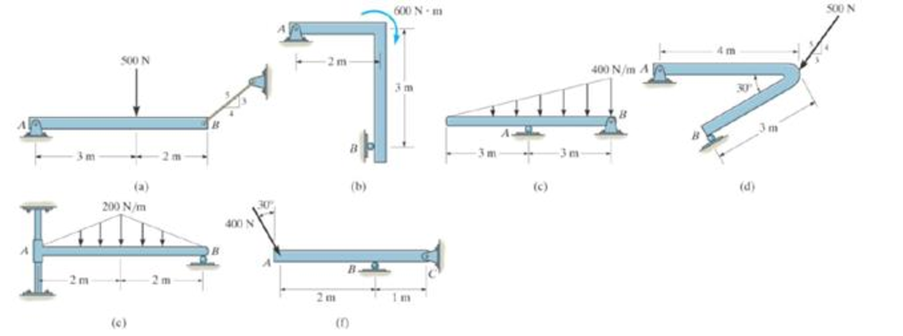
Prob. P5-1
Expert Solution & Answer

Learn your wayIncludes step-by-step video

schedule04:44
Students have asked these similar questions
AAA
Show laplace transform on 1; (+) to L (y(+)) : SY(s) = x (0)
Y(s) = £ [lx (+)] = 5 x(+) · est de
2
-St
L [ y (^) ] = So KG) et de
D
2
D
D
AA
Y(A) → Y(s)
Ŷ (+) → s Y(s)
-y
1) In each of the following scenarios, based on the plane of impact (shown with an (n, t)) and the
motion of mass 1, draw the direction of motion of mass 2 after the impact. Note that in all
scenarios, mass 2 is initially at rest. What can you say about the nature of the motion of mass 2
regardless of the scenario?
m1
15
<+
m2
2)
y
"L
χ
m1
m2
m1
בז
m2
F
8. In the following check to see if the set S is a vector subspace of the corresponding Rn. If
it is not, explain why not. If it is, then find a basis and the dimension.
X1
(a) S
=
X2
{[2], n ≤ n } c
X1 X2
CR²
X1
(b) S
X2
=
X3
X4
x1 + x2 x3 = 0
Chapter 5 Solutions
Engineering Mechanics: Statics, Student Value Edition; Modified Mastering Engineering with Pearson eText -- Standalone Access Card -- for Engineering Mechanics: Statics (14th Edition)
Ch. 5.2 - Draw the free-body diagram for the following...Ch. 5.2 - Draw the free-body diagram for the following...Ch. 5.2 - Draw the free-body diagram for the following...Ch. 5.2 - Draw the free-body diagram for the following...Ch. 5.2 - Draw the free-body diagram for the following...Ch. 5.2 - Draw the free-body diagram for the following...Ch. 5.2 - Draw the free-body diagram for the following...Ch. 5.2 - Draw the free-body diagram for the following...Ch. 5.2 - Draw the free-body diagram for the following...Ch. 5.4 - Draw the free body diagram of each object. Prob....
Ch. 5.4 - Determine the horizontal and vertical components...Ch. 5.4 - Determine the horizontal and vertical components...Ch. 5.4 - The truss is supported by a pin at A and a roller...Ch. 5.4 - Determine the components of reaction at the fixed...Ch. 5.4 - The 25 kg bar has a center of mass at G. If it is...Ch. 5.4 - Determine the reactions at the smooth contact...Ch. 5.4 - Determine the components of the support reactions...Ch. 5.4 - Determine the reactions at the supports. Prob....Ch. 5.4 - Determine the horizontal and vertical components...Ch. 5.4 - Determine the reactions at the supports. Prob....Ch. 5.4 - Determine the reactions at the supports. Prob....Ch. 5.4 - Determine the reactions at the supports. Prob....Ch. 5.4 - Determine the tension in the cable and the...Ch. 5.4 - The man attempts to a up port the toad of boards...Ch. 5.4 - Determine the components of reaction at the...Ch. 5.4 - The man has a weight W and stands at the center of...Ch. 5.4 - A uniform glass rod having a length L is placed in...Ch. 5.4 - The uniform rod AB has a mass of 40 kg. Determine...Ch. 5.4 - If the intensity of the distributed load acting on...Ch. 5.4 - If the roller at A and the pin at B can support a...Ch. 5.4 - The relay regulates voltage and current. Determine...Ch. 5.4 - Determine the reactions on the bent rod which is...Ch. 5.4 - The mobile crane is symmetrically supported by two...Ch. 5.4 - Determine the reactions acting on the smooth...Ch. 5.4 - A linear torsional spring deforms such that an...Ch. 5.4 - Determine the force P needed to pull the 50-kg...Ch. 5.4 - Determine the magnitude and direction of the...Ch. 5.4 - The operation of the fuel pump for an automobile...Ch. 5.4 - Determine the magnitude of force at the pin A and...Ch. 5.4 - The dimensions of a jib crane, which is...Ch. 5.4 - The dimensions of a jib crane, which is...Ch. 5.4 - The smooth pipe rests against the opening at the...Ch. 5.4 - The beam of negligible weight is supported...Ch. 5.4 - The cantilevered jib crane is used to support the...Ch. 5.4 - The cantilevered jib crane is used to support the...Ch. 5.4 - The bar of negligible weight is supported by two...Ch. 5.4 - Determine the stiffness k of each spring so that...Ch. 5.4 - The bulk head AD Is subjected to both water and...Ch. 5.4 - The boom supports the two vertical loads. Neglect...Ch. 5.4 - The boom is intended to support two vertical loads...Ch. 5.4 - The 10-kg uniform rod is pinned at end A. If It is...Ch. 5.4 - If the truck and its contents have a mass of 50 kg...Ch. 5.4 - Three uniform books each having a weight W and...Ch. 5.4 - Determine the reactions at the pin A and the...Ch. 5.4 - If rope BC will fail when the tension becomes 50...Ch. 5.4 - The rigid metal strip of negligible weight is used...Ch. 5.4 - The rigid metal strip of negligible weight is used...Ch. 5.4 - The cantilever footing is used to support a wail...Ch. 5.4 - The uniform beam has a weight Wand length l and is...Ch. 5.4 - A boy stands out at the end of the diving board,...Ch. 5.4 - The 30-N uniform rod has a length of l = 1 m. If s...Ch. 5.4 - The uniform rod has a length I and weight W. It is...Ch. 5.4 - I he uniform rod of length L and weight W is...Ch. 5.4 - Assuming that the foundation exerts a linearly...Ch. 5.4 - Assuming that the foundation exerts a linearly...Ch. 5.4 - If it is also subjected to a couple moment of 100...Ch. 5.4 - Determine the distance d for placement of the load...Ch. 5.4 - If d = 1 m, and = 30, determine me normal...Ch. 5.4 - The man attempts to pull the tour wheeler up the...Ch. 5.4 - Where is the best place to arrange most of the...Ch. 5.7 - Draw the free-body diagram of each object.Ch. 5.7 - In each case, write the moment equations about the...Ch. 5.7 - The uniform plate has a weight of 500 lb....Ch. 5.7 - Determine the reactions at the roller support A,...Ch. 5.7 - The rod is supported by smooth journal bearings at...Ch. 5.7 - Determine the support reactions at the smooth...Ch. 5.7 - Determine the force developed in the short link...Ch. 5.7 - Determine the components of reaction that the...Ch. 5.7 - Determine the tension each rope and the force that...Ch. 5.7 - If these components have weights WA = 45000 Wa =...Ch. 5.7 - Determine the components of reaction at the fixed...Ch. 5.7 - Determine the vertical reactions at the wheels C...Ch. 5.7 - Determine the components of reaction at A, the...Ch. 5.7 - Determine the tension in each of the three...Ch. 5.7 - Determine the components of reaction at hinges A...Ch. 5.7 - Determine me tension in each cable and the...Ch. 5.7 - The cables are attached to a smooth collar ring at...Ch. 5.7 - Determine the components of reaction at the...Ch. 5.7 - Determine the components of reaction at the...Ch. 5.7 - Determine the components of reaction at the...Ch. 5.7 - Determine the magnitude of F which will cause the...Ch. 5.7 - Determine the components of reaction at A and the...Ch. 5.7 - Determine the components of reaction at these...Ch. 5.7 - Determine the components or reaction at these...Ch. 5.7 - Compute the x, y, z components of reaction at the...Ch. 5.7 - Determine the magnitude of F2 which will cause the...Ch. 5.7 - At A the connection is with a ball-and-socket....Ch. 5.7 - If it is supported by a ball-and-socket joint at C...Ch. 5.7 - Determine the x, y, z components of reaction at...Ch. 5.7 - Determine the horizontal tension T in the belt on...Ch. 5.7 - Determine the horizontal tension T in the belt on...Ch. 5.7 - Determine the components of reaction at A and the...Ch. 5.7 - If the roller at 8 can sustain a maximum load of 3...Ch. 5.7 - Determine the reactions at the supports A and B...Ch. 5.7 - Determine the normal reaction at the roller A and...Ch. 5.7 - Determine the horizontal and vertical components...Ch. 5.7 - Determine the x, y, z components of reaction at...Ch. 5.7 - Determine the horizontal equilibrium force P that...Ch. 5.7 - Determine the x, y, z components of reaction at...Ch. 5.7 - Determine the x and z components of reaction at...
Additional Engineering Textbook Solutions
Find more solutions based on key concepts
The data shown in the following graph was collected during testing of an electromagnetic mass driver. The energ...
Thinking Like an Engineer: An Active Learning Approach (4th Edition)
What are the five basic joint tvpes for fusion welding?
Degarmo's Materials And Processes In Manufacturing
What populates the Smalltalk world?
Concepts Of Programming Languages
Distinguish among data definition commands, data manipulation commands, and data control commands.
Modern Database Management
Figure 1-30 shows the Visual Studio IDE. What are the names of the four areas indicated in the figure? Figure 1...
Starting Out With Visual Basic (8th Edition)
Car Instrument Simulator For this assignment, you will design a set of classes that work together to simulate a...
Starting Out with Java: From Control Structures through Objects (7th Edition) (What's New in Computer Science)
Knowledge Booster


Learn more about
Need a deep-dive on the concept behind this application? Look no further. Learn more about this topic, mechanical-engineering and related others by exploring similar questions and additional content below.Similar questions
- 2) Suppose that two unequal masses m₁ and m₂ are moving with initial velocities V₁ and V₂, respectively. The masses hit each other and have a coefficient of restitution e. After the impact, mass 1 and 2 head to their respective gaps at angles a and ẞ, respectively. Derive expressions for each of the angles in terms of the initial velocities and the coefficient of restitution. m1 m2 8 m1 ↑ บา m2 ñ Вarrow_forwardThe fallowing question is from a reeds book on applied heat i am studying. Although the answer is provided, im struggling to understand the whole answer and the formulas and the steps theyre using. Also where some ov the values such as Hg and Hf come from in part i for example. Please explain step per step in detail thanks In an NH, refrigerator, the ammonia leaves the evaporatorand enters the cornpressor as dry saturated vapour at 2.68 bar,it leaves the compressor and enters the condenser at 8.57 bar with50" of superheat. it is condensed at constant pressure and leavesthe condenser as saturated liquid. If the rate of flow of the refrigerantthrough the circuit is 0.45 kglmin calculate (i) the compressorpower, (ii) the heat rejected to the condenser cooling water in kJ/s,an (iii) the refrigerating effect in kJ/s. From tables page 12, NH,:2.68 bar, hg= 1430.58.57 bar, hf = 275.1 h supht 50" = 1597.2Mass flow of refrigerant--- - - 0.0075 kgls 60Enthalpy gain per kg of refrigerant in…arrow_forwardstate the formulas for calculating work done by gasarrow_forward
- Exercises Find the solution of the following Differential Equations 1) y" + y = 3x² 3) "+2y+3y=27x 5) y"+y=6sin(x) 7) y"+4y+4y = 18 cosh(x) 9) (4)-5y"+4y = 10 cos(x) 11) y"+y=x²+x 13) y"-2y+y=e* 15) y+2y"-y'-2y=1-4x³ 2) y"+2y' + y = x² 4) "+y=-30 sin(4x) 6) y"+4y+3y=sin(x)+2 cos(x) 8) y"-2y+2y= 2e* cos(x) 10) y+y-2y=3e* 12) y"-y=e* 14) y"+y+y=x+4x³ +12x² 16) y"-2y+2y=2e* cos(x)arrow_forwardThe state of stress at a point is σ = -4.00 kpsi, σy = 16.00 kpsi, σ = -14.00 kpsi, Try = 11.00 kpsi, Tyz = 8.000 kpsi, and T = -14.00 kpsi. Determine the principal stresses. The principal normal stress σ₁ is determined to be [ The principal normal stress σ2 is determined to be [ The principal normal stress σ3 is determined to be kpsi. kpsi. The principal shear stress 71/2 is determined to be [ The principal shear stress 7½ is determined to be [ The principal shear stress T₁/, is determined to be [ kpsi. kpsi. kpsi. kpsi.arrow_forwardRepeat Problem 28, except using a shaft that is rotatingand transmitting a torque of 150 N * m from the left bearing to the middle of the shaft. Also, there is a profile keyseat at the middle under the load. (I want to understand this problem)arrow_forward
- Prob 2. The material distorts into the dashed position shown. Determine the average normal strains &x, Ey and the shear strain Yxy at A, and the average normal strain along line BE. 50 mm B 200 mm 15 mm 30 mm D ΕΙ 50 mm x A 150 mm Farrow_forwardProb 3. The triangular plate is fixed at its base, and its apex A is given a horizontal displacement of 5 mm. Determine the shear strain, Yxy, at A. Prob 4. The triangular plate is fixed at its base, and its apex A is given a horizontal displacement of 5 mm. Determine the average normal strain & along the x axis. Prob 5. The triangular plate is fixed at its base, and its apex A is given a horizontal displacement of 5 mm. Determine the average normal strain &x along the x' axis. x' 45° 800 mm 45° 45% 800 mm 5 mmarrow_forwardAn airplane lands on the straight runaway, originally travelling at 110 ft/s when s = 0. If it is subjected to the decelerations shown, determine the time t' needed to stop the plane and construct the s -t graph for the motion. draw a graph and show all work step by steparrow_forward
- dny dn-1y dn-1u dn-24 +a1 + + Any = bi +b₂- + +bnu. dtn dtn-1 dtn-1 dtn-2 a) Let be a root of the characteristic equation 1 sn+a1sn- + +an = : 0. Show that if u(t) = 0, the differential equation has the solution y(t) = e\t. b) Let к be a zero of the polynomial b(s) = b₁s-1+b2sn−2+ Show that if the input is u(t) equation that is identically zero. = .. +bn. ekt, then there is a solution to the differentialarrow_forwardB 60 ft WAB AB 30% : The crane's telescopic boom rotates with the angular velocity w = 0.06 rad/s and angular acceleration a = 0.07 rad/s². At the same instant, the boom is extending with a constant speed of 0.8 ft/s, measured relative to the boom. Determine the magnitude of the acceleration of point B at this instant.arrow_forwardThe motion of peg P is constrained by the lemniscate curved slot in OB and by the slotted arm OA. (Figure 1) If OA rotates counterclockwise with a constant angular velocity of 0 = 3 rad/s, determine the magnitude of the velocity of peg P at 0 = 30°. Express your answer to three significant figures and include the appropriate units. Determine the magnitude of the acceleration of peg P at 0 = 30°. Express your answer to three significant figures and include the appropriate units. 0 (4 cos 2 0)m² B Aarrow_forward
arrow_back_ios
SEE MORE QUESTIONS
arrow_forward_ios
Recommended textbooks for you
 International Edition---engineering Mechanics: St...Mechanical EngineeringISBN:9781305501607Author:Andrew Pytel And Jaan KiusalaasPublisher:CENGAGE L
International Edition---engineering Mechanics: St...
Mechanical Engineering
ISBN:9781305501607
Author:Andrew Pytel And Jaan Kiusalaas
Publisher:CENGAGE L
Dynamics - Lesson 1: Introduction and Constant Acceleration Equations; Author: Jeff Hanson;https://www.youtube.com/watch?v=7aMiZ3b0Ieg;License: Standard YouTube License, CC-BY