
VECTOR MECH. FOR EGR: STATS & DYNAM (LL
12th Edition
ISBN: 9781260663778
Author: BEER
Publisher: MCG
expand_more
expand_more
format_list_bulleted
Videos
Textbook Question
Chapter 5.3, Problem 5.95P
The square gate AB is held in the position shown by hinges along its top edge A and by a shear pin at B. For a depth of water d = 3.5 ft, determine the force exerted on the gate by the shear pin.
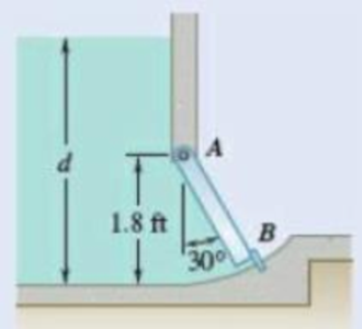
Fig. P5.95
Expert Solution & Answer
Want to see the full answer?
Check out a sample textbook solution
Students have asked these similar questions
a problem existed at the stocking stations of a mini-load AS/RS (automated storage and retrieval system) of a leading electronics manufacturer (Fig.1). At these stations, operators fill the bin delivered by the crane with material arriving in a tote over a roller conveyor. The conveyor was designed at such a height that it was impossible to reach the hooks comfortably even with the tote extended. Furthermore, cost consideration came into the picture and the conveyor height was not reduced. Instead, a step stool was considered to enable the stocker to reach the moving hooks comfortably. The height of the hooks from the floor is 280.2 cm (AD). The tote length is 54.9 cm. The projection of tote length and arm reach, CB = 66.1 cm. a) What anthropometric design principles would you follow to respectively calculate height, length, and width of the step to make it usable to a large number of people? b) What is the minimum height (EF) of the step with no shoe allowance? c) What is the minimum…
Qu. 5 Composite materials are becoming more widely used in aircraft industry due to their high strength, low weight and excellent corrosion resistant properties. As an engineer who is given task to design the I beam section of an aircraft (see Figure 7) please, answer the following questions given the material properties in Table 3.
Determine the Moduli of Elasticity of Carbon/Epoxy, Aramid/Epoxy, and Boron /Epoxy composites in the longitudinal direction, given that the composites consist of 25 vol% epoxy and 75 vol% fiber.
What are the specific moduli of each of these composites?
What are the specific strengths (i.e. specific UTS) of each of these composites?
What is the final cost of each of these composites?please show all work step by step problems make sure to see formula material science
Mueh
Battery operated train
Coll
160,000kg 0.0005 0.15 5m² 1.2kg/m³
CD
Af Pair
19
пре neng
0.98 0.9
0.88
Tesla Prated
Tesla Trated "wheel ng
Joxle
270 kW
440NM
0,45m 20
8.5kg m2
the middle
Consider a drive cycle of a 500km trip with 3 stops in
Other than the acceleration and deceleration
associated with the three stops, the tran maintains
constat cruise speed velocity of 324 km/hr. The
tran will fast charge at each stop for 15 min at a
rate Peharge = 350 kW
ΟΙ
15MIN
Stop
w charging
(350kW)
(ผม
τ
(AN
GMIJ
t
6M
1) HOW MUCH DISTANCE dace is covered DURING THE
ACCELERATION TO 324 km/hr?
2)
DETERMINE HOW LONG (IN seconds) the tran will
BE TRAVELING AT FULL SPEED
2
?
3) CALCULATE THE NET ENERGY GAW PER STOP
ete
Chapter 5 Solutions
VECTOR MECH. FOR EGR: STATS & DYNAM (LL
Ch. 5.1 - 5.1 through 5.9 Locate the centroid of the plane...Ch. 5.1 - Locate the centroid of the plane area shown.Ch. 5.1 - Locate the centroid of the plane area shown.Ch. 5.1 - Locate the centroid of the plane area shown.Ch. 5.1 - Locate the centroid of the plane area shown.Ch. 5.1 - Locate the centroid of the plane area shown.Ch. 5.1 - Locate the centroid of the plane area shown.Ch. 5.1 - Locate the centroid of the plane area shown.Ch. 5.1 - Locate the centroid of the plane area shown.Ch. 5.1 - Locate the centroid of the plane area shown.
Ch. 5.1 - Locate the centroid of the plane area shown.Ch. 5.1 - Locate the centroid of the plane area shown.Ch. 5.1 - Locate the centroid of the plane area shown.Ch. 5.1 - Locate the centroid of the plane area shown.Ch. 5.1 - Locate the centroid of the plane area shown.Ch. 5.1 - PROBLEM 5.16 Determine the y coordinate of the...Ch. 5.1 - Show that as r1 approaches r2, the location of the...Ch. 5.1 - Prob. 5.18PCh. 5.1 - Prob. 5.19PCh. 5.1 - A built-up beam is constructed by nailing seven...Ch. 5.1 - The horizontal x axis is drawn through the...Ch. 5.1 - The horizontal x-axis is drawn through the...Ch. 5.1 - PROBLEM 5.23 The first moment of the shaded area...Ch. 5.1 - A thin, homogeneous wire is bent to form the...Ch. 5.1 - A thin, homogeneous wire is bent to form the...Ch. 5.1 - Prob. 5.26PCh. 5.1 - A thin, homogeneous wire is bent to form the...Ch. 5.1 - Prob. 5.28PCh. 5.1 - The frame for a sign is fabricated from thin, flat...Ch. 5.1 - The homogeneous wire ABCD is bent as shown and is...Ch. 5.1 - The homogeneous wire ABCD is bent as shown and is...Ch. 5.1 - Prob. 5.32PCh. 5.1 - Knowing that the distance h has been selected to...Ch. 5.2 - Determine by direct integration the centroid of...Ch. 5.2 - 5.34 through 5.36 Determine by direct integration...Ch. 5.2 - 5.34 through 5.36 Determine by direct integration...Ch. 5.2 - 5.37 through 5.39 Determine by direct integration...Ch. 5.2 - 5.37 through 5.39 Determine by direct integration...Ch. 5.2 - Prob. 5.39PCh. 5.2 - 5.40 and 5.41 Determine by direct integration the...Ch. 5.2 - 5.40 and 5.41 Determine by direct integration the...Ch. 5.2 - 5.42 Determine by direct integration the centroid...Ch. 5.2 - 5.43 and 5.44 Determine by direct integration the...Ch. 5.2 - 5.43 and 5.44 Determine by direct integration the...Ch. 5.2 - 5.45 and 5.46 A homogeneous wire is bent into the...Ch. 5.2 - 5.45 and 5.46 A homogeneous wire is bent into the...Ch. 5.2 - A homogeneous wire is bent into the shape shown....Ch. 5.2 - 5.48 and 5.49 Determine by direct integration the...Ch. 5.2 - Prob. 5.49PCh. 5.2 - Prob. 5.50PCh. 5.2 - Determine the centroid of the area shown when a =...Ch. 5.2 - Determine the volume and the surface area of the...Ch. 5.2 - Determine the volume and the surface area of the...Ch. 5.2 - Determine the volume and the surface area of the...Ch. 5.2 - Determine the volume and the surface area of the...Ch. 5.2 - Determine the volume of the solid generated by...Ch. 5.2 - Prob. 5.57PCh. 5.2 - Prob. 5.58PCh. 5.2 - Prob. 5.59PCh. 5.2 - Determine the capacity, in liters, of the punch...Ch. 5.2 - Determine the volume and total surface area of the...Ch. 5.2 - Prob. 5.62PCh. 5.2 - Determine the total surface area of the solid...Ch. 5.2 - Determine the volume of the brass collar obtained...Ch. 5.2 - The shade for a wall-mounted light is formed from...Ch. 5.3 - 5.66 and 5.67 For the beam and loading shown,...Ch. 5.3 - 5.66 and 5.67 For the beam and loading shown,...Ch. 5.3 - 5.68 through 5.73 Determine the reactions at the...Ch. 5.3 - 5.68 through Determine the reactions at the beam...Ch. 5.3 - 5.68 through 5.73 Determine the reactions at the...Ch. 5.3 - 5.68 through Determine the reactions at the beam...Ch. 5.3 - 5.68 through 5.73 Determine the reactions at the...Ch. 5.3 - 5.68 through 5.73 Determine the reactions at the...Ch. 5.3 - Determine (a) the distance a so that the vertical...Ch. 5.3 - Prob. 5.75PCh. 5.3 - Determine the reactions at the beam supports for...Ch. 5.3 - Determine (a) the distributed load w0 at the end D...Ch. 5.3 - The beam AB supports two concentrated loads and...Ch. 5.3 - For the beam and loading of Prob. 5.78, determine...Ch. 5.3 - The cross section of a concrete dam is as shown....Ch. 5.3 - Prob. 5.81PCh. 5.3 - The dam for a lake is designed to withstand the...Ch. 5.3 - Prob. 5.83PCh. 5.3 - The friction force between a 6 6-ft square sluice...Ch. 5.3 - A freshwater marsh is drained to the ocean through...Ch. 5.3 - Prob. 5.86PCh. 5.3 - The 3 4-m side of an open tank is hinged at its...Ch. 5.3 - Prob. 5.88PCh. 5.3 - A 0.5 0.8-m gate AB is located at the bottom of a...Ch. 5.3 - Prob. 5.90PCh. 5.3 - Prob. 5.91PCh. 5.3 - Prob. 5.92PCh. 5.3 - Prob. 5.93PCh. 5.3 - Prob. 5.94PCh. 5.3 - The square gate AB is held in the position shown...Ch. 5.4 - Consider the composite body shown. Determine (a)...Ch. 5.4 - A cone and a cylinder of the same radius a and...Ch. 5.4 - Determine the location of the center of gravity of...Ch. 5.4 - Prob. 5.99PCh. 5.4 - For the stop bracket shown, locate the x...Ch. 5.4 - Fig. P5.100 and P5.101 5.101 For the stop bracket...Ch. 5.4 - For the machine element shown, locate the x...Ch. 5.4 - Fig. P5.102 and P5.103 5.103 For the machine...Ch. 5.4 - For the machine element shown, locate the y...Ch. 5.4 - For the machine element shown, locate the x...Ch. 5.4 - 5.106 and 5.107 Locate the center of gravity of...Ch. 5.4 - 5.106 and 5.107 Locate the center of gravity of...Ch. 5.4 - A corner reflector for tracking by radar has two...Ch. 5.4 - A wastebasket, designed to fit in the corner of a...Ch. 5.4 - Prob. 5.110PCh. 5.4 - Prob. 5.111PCh. 5.4 - Prob. 5.112PCh. 5.4 - Locate the center of gravity of the sheet-metal...Ch. 5.4 - A thin steel wire with a uniform cross section is...Ch. 5.4 - The frame of a greenhouse is constructed from...Ch. 5.4 - Locate the center of gravity of the figure shown,...Ch. 5.4 - PROBLEM 5.117 Locate the center of gravity of the...Ch. 5.4 - A scratch awl has a plastic handle and a steel...Ch. 5.4 - Prob. 5.119PCh. 5.4 - PROBLEM 5.120 A brass collar, of length 2.5 in.,...Ch. 5.4 - Prob. 5.121PCh. 5.4 - Prob. 5.122PCh. 5.4 - Prob. 5.123PCh. 5.4 - Prob. 5.124PCh. 5.4 - PROBLEM 5.125 Locate the centroid of the volume...Ch. 5.4 - PROBLEM 5.126 Locate the centroid of the volume...Ch. 5.4 - Prob. 5.127PCh. 5.4 - Prob. 5.128PCh. 5.4 - PROBLEM 5.129 Locate the centroid of the volume...Ch. 5.4 - Prob. 5.130PCh. 5.4 - Prob. 5.131PCh. 5.4 - PROBLEM 5.132 The sides and the base of a punch...Ch. 5.4 - Locate the centroid of the section shown, which...Ch. 5.4 - Prob. 5.134PCh. 5.4 - Prob. 5.135PCh. 5.4 - Alter grading a lot, a builder places four stakes...Ch. 5 - 5.137 and 5.138 Locate the centroid of the plane...Ch. 5 - 5.137 and 5.138 Locate the centroid of the plane...Ch. 5 - Prob. 5.139RPCh. 5 - Prob. 5.140RPCh. 5 - Prob. 5.141RPCh. 5 - Prob. 5.142RPCh. 5 - Determine the reactions at the supports for the...Ch. 5 - A beam is subjected to a linearly distributed...Ch. 5 - Prob. 5.145RPCh. 5 - Prob. 5.146RPCh. 5 - An 8-in.-diameter cylindrical duct and a 4 8-in....Ch. 5 - Three brass plates are brazed to a steel pipe to...
Knowledge Booster


Learn more about
Need a deep-dive on the concept behind this application? Look no further. Learn more about this topic, mechanical-engineering and related others by exploring similar questions and additional content below.Similar questions
- Please stop screenshoting ai solution,it always in accurate solve normalarrow_forwardResearch and select any different values for the Ratio of connecting rod length to crank radius from various engine models, then analyze how these changes affect instantaneous velocity and acceleration, presenting your findings visually using graphs.arrow_forwardPb 9) 4.44 bas gnibus& WX 002 grillimatul fred bail (e) For the simply supported I-beam, a load of 1000 lb in center. Find the maximum transverse shear stress. Compare your answer with the approximation obtained by dividing the shear load by the area of the web only with the web considered to extend for the full 8-in depth. - 3½ in. 12 bas in 0% to tolerabib tormi no grived in. 8 in. 38 in. 12 ½ in.arrow_forward
- Pb 12) 4.61 Draw the Mohr circle for the stresses experienced by the surface of an internally pressurized steel tube that is subject to the tangential and axial stresses in the outer surface of 45 ksi and 30 ksi, respectively, and a torsional stress of 18 ksi. yx 18 45 30arrow_forwardPb 8) 4.39 For the C-clamp shown, what force F can be exerted by the screw if the maximum tensile stress in the clamp is to be limited to 30 ksi? F 2 in. სის 3436 16 13 blos 0101 alos12 nodus 121A (s 3 in. in. 16 in. 16 web leonas OFF elson yollA (d 016 (& d of bolow-bloo ai 15912 020112LA sue) vilisub 22 bal.90 Swman a bris ctxibasqqA) laste is tools?arrow_forwardQuiz/An eccentrically loaded bracket is welded to the support as shown in Figure below. The load is static. The weld size for weld w1 is h1 = 6mm, for w2 h2 = 5mm, and for w3 is h3 =5.5 mm. Determine the safety factor (S.f) for the welds. F=22 kN. Use an AWS Electrode type (E90xx). 140 S Find the centroid I want university professor solutions O REDMI NOTE 8 PRO CAI QUAD CAMERA 101.15 Farrow_forward
- Pb 6) 4.31 do = 25 mm 4.31 What bending moment is required to produce a maximum normal stress of 400 MPa: (a) In a straight round rod of 40-mm diameter? (b) In a straight square rod, 40 mm on a side (with bending about the X axis as shown for a rectangular section in Appendix B-2)?arrow_forwardPb 13) 4.73 Find the maximum value of stress at the hole and semicircular notch. 45000 N 50 mm 100 mm 15 mm 25 mm 45000 Narrow_forwardPb 11) 4.53 Consider the 1-in solid round shaft supported by self-aligning bearings at A and B. Attached to the shaft are two chain sprockets that are loaded as shown. Treat this as a static loading problem and identify the specific shat location subjected to the most severe state of stress and make a Mohr circle representation of this stress state. 1-in.-dia. shaft 500 lb 2 in. 1000 lb 3 in. 3 in.arrow_forward
- Pb 5) 4.19 Estimate the torque required to produce a maximum shear stress of 570 MPa in a hollow shaft having an inner diameter of 20 mm and an outer diameter of 25 mm. d; = 20 mm T d = 25 mm Tmax = 570 MPaarrow_forwardQuiz/An eccentrically loaded bracket is welded to the support as shown in Figure below. The load is static. The weld size for weld w1 is h1 = 6mm, for w2 h2 = 5mm, and for w3 is h3 =5.5 mm. Determine the safety factor (S.f) for the welds. F=22 kN. Use an AWS Electrode type (E90xx). I want university professor solutions O REDMI NOTE 8 PRO CAI QUAD CAMERA 140 S 101.15 Farrow_forwardResearch and select different values for the R ratio from various engine models, then analyze how these changes affect instantaneous velocity and acceleration, presenting your findings visually using graphsarrow_forward
arrow_back_ios
SEE MORE QUESTIONS
arrow_forward_ios
Recommended textbooks for you
 Elements Of ElectromagneticsMechanical EngineeringISBN:9780190698614Author:Sadiku, Matthew N. O.Publisher:Oxford University Press
 Mechanics of Materials (10th Edition)Mechanical EngineeringISBN:9780134319650Author:Russell C. HibbelerPublisher:PEARSON
 Thermodynamics: An Engineering ApproachMechanical EngineeringISBN:9781259822674Author:Yunus A. Cengel Dr., Michael A. BolesPublisher:McGraw-Hill Education
 Control Systems EngineeringMechanical EngineeringISBN:9781118170519Author:Norman S. NisePublisher:WILEY
 Mechanics of Materials (MindTap Course List)Mechanical EngineeringISBN:9781337093347Author:Barry J. Goodno, James M. GerePublisher:Cengage Learning
 Engineering Mechanics: StaticsMechanical EngineeringISBN:9781118807330Author:James L. Meriam, L. G. Kraige, J. N. BoltonPublisher:WILEY
Elements Of Electromagnetics
Mechanical Engineering
ISBN:9780190698614
Author:Sadiku, Matthew N. O.
Publisher:Oxford University Press
Mechanics of Materials (10th Edition)
Mechanical Engineering
ISBN:9780134319650
Author:Russell C. Hibbeler
Publisher:PEARSON
Thermodynamics: An Engineering Approach
Mechanical Engineering
ISBN:9781259822674
Author:Yunus A. Cengel Dr., Michael A. Boles
Publisher:McGraw-Hill Education
Control Systems Engineering
Mechanical Engineering
ISBN:9781118170519
Author:Norman S. Nise
Publisher:WILEY
Mechanics of Materials (MindTap Course List)
Mechanical Engineering
ISBN:9781337093347
Author:Barry J. Goodno, James M. Gere
Publisher:Cengage Learning
Engineering Mechanics: Statics
Mechanical Engineering
ISBN:9781118807330
Author:James L. Meriam, L. G. Kraige, J. N. Bolton
Publisher:WILEY
Physics 33 - Fluid Statics (1 of 10) Pressure in a Fluid; Author: Michel van Biezen;https://www.youtube.com/watch?v=mzjlAla3H1Q;License: Standard YouTube License, CC-BY