
Concept explainers
Videos
(a)
The reaction forces exerted by the ground on the base of the concrete dam
(a)
Answer to Problem 5.81P
The resultant reaction forces acts on the base of the dam is
Explanation of Solution
Given that the width of the dam section
The free-body diagram consists of dam and the triangular section
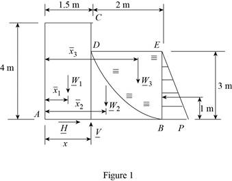
The length
Write the equation for weight force acts on the dam.
Here, the weight of the dam is
Replace
Here, the thickness of the dam section is
Write the equation for the weight of the dam represented by the weights of its components.
Here, the weight of the dam by the components of fist section is
Substitute
Write the equation for the weight of the dam represented in the triangular section.
Here, the weight of the dam by the components of second section is
Substitute
Write the equation for the weight of the dam represented in the parabola section by the weights of its components.
Here, the weight of the dam by the components of third section is
Substitute
Write the equation of the force pressure exerted by the ground on the base of the dam.
Here, the reaction force exerted on the dam is
Replace
Write the equilibrium equation for the section of dam acts along x axis (Refer Fig 1).
Here, the reaction force exerted by the ground on the base
Write the equilibrium equation for the section of beam acts along y axis and then calculate the reaction force (Refer Fig 1).
Here, the reaction force exerted by the ground on the base
Conclusion:
Substitute
Substitute
Substitute
Therefore, the resultant reaction forces acts on the base of the dam is
(b)
The point of forces acts on the base
(b)
Answer to Problem 5.81P
The point in which the forces acts on the base
Explanation of Solution
The distance from the base of the dam to the point
The distance from the base of the dam to the side
The distance from the base of the dam to the point
Write the equilibrium equation for the section on the base
Here, the different section of the dam is represented as
Conclusion:
Substitute
Solve the above equation for
Therefore, the point in which the forces acts on the base
(c)
The resultant pressure force exerted by the water on the face
(c)
Answer to Problem 5.81P
The resultant pressure force exerted by the water on the face
Explanation of Solution
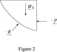
The free body diagram of the water section
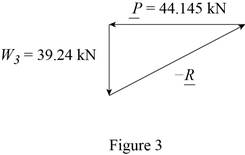
Write the equilibrium equation for the s resultant pressure force exerted by the water on the face
Here, the resultant pressure force exerted by the water on the dam is
Solve for the angle of resultant force exerted by the water on the dam by using trigonometric relation (Refer fig 3).
Conclusion:
Substitute
Substitute
Therefore, the resultant pressure force exerted by the water on the face
Want to see more full solutions like this?
Chapter 5 Solutions
Vector Mechanics for Engineers: Statics and Dynamics


- Q | Sign in PDE Lecture W09.pdf PDF MMB241 - Tutorial L9.pdi X PDF MMB241 - Tutorial L10.p X PDF MMB241 - Tutorial L11.p X Lecture W12-Work and X + File C:/Users/KHULEKANI/Desktop/mmb241/Lecture%20W12%20-%20Work%20and%20Energy.pdf ||! Draw | IA | a | Ask Copilot Class Work + 33 of 34 D Question 1 The engine of a 3500-N car is generating a constant power of 50 hp (horsepower) while the car is traveling up the slope with a constant speed. If the engine is operating with an efficiency of € 0.8, determine the speed of the car. Neglect drag and rolling resistance. Use g 9.81 m/s² and 1 hp = 745.7 W. 10 го Question 2 A man pushes on a 60-N crate with a force F. The force is always directed downward at an angle of 30° from the horizontal, as shown in the figure. The magnitude of the force is gradually increased until the crate begins to slide. Determine the crate's initial acceleration once it starts to move. Assume the coefficient of static friction is μ = 0.6, the coefficient of kinetic…arrow_forwardstate is Derive an expression for the volume expansivity of a substance whose equation of RT P = v-b a v(v + b)TZ where a and b are empirical constants.arrow_forwardFor a gas whose equation of state is P(v-b)=RT, the specified heat difference Cp-Cv is equal to which of the following (show all work): (a) R (b) R-b (c) R+b (d) 0 (e) R(1+v/b)arrow_forward
- of state is Derive an expression for the specific heat difference of a substance whose equation RT P = v-b a v(v + b)TZ where a and b are empirical constants.arrow_forwardTemperature may alternatively be defined as T = ди v Prove that this definition reduces the net entropy change of two constant-volume systems filled with simple compressible substances to zero as the two systems approach thermal equilibrium.arrow_forwardUsing the Maxwell relations, determine a relation for equation of state is (P-a/v²) (v−b) = RT. Os for a gas whose av Tarrow_forward
- (◉ Homework#8arrow_forwardHomework#8arrow_forwardBox A has a mass of 15 kilograms and is attached to the 20 kilogram Box B using the cord and pulley system shown. The coefficient of kinetic friction between the boxes and surface is 0.2 and the moment of inertia of the pulley is 0.5 kg * m^ 2. After 2 seconds, how far do the boxes move? A бро Barrow_forwardBox A has a mass of 15 kilograms and is attached to the 20 kilogram Box B using the cord and pulley system shown. The coefficient of kinetic friction between the boxes and surface is 0.2 and the moment of inertia of the pulley is 0.5 kg * m^2. Both boxes are 0.25 m long and 0.25 m high. The cord is attached to the bottom of Box A and the middle of box B. After 2 seconds, how far do the boxes move? A From бро Barrow_forwardarrow_back_iosSEE MORE QUESTIONSarrow_forward_iosRecommended textbooks for you
 Elements Of ElectromagneticsMechanical EngineeringISBN:9780190698614Author:Sadiku, Matthew N. O.Publisher:Oxford University Press
 Mechanics of Materials (10th Edition)Mechanical EngineeringISBN:9780134319650Author:Russell C. HibbelerPublisher:PEARSON
 Thermodynamics: An Engineering ApproachMechanical EngineeringISBN:9781259822674Author:Yunus A. Cengel Dr., Michael A. BolesPublisher:McGraw-Hill Education
 Control Systems EngineeringMechanical EngineeringISBN:9781118170519Author:Norman S. NisePublisher:WILEY
 Mechanics of Materials (MindTap Course List)Mechanical EngineeringISBN:9781337093347Author:Barry J. Goodno, James M. GerePublisher:Cengage Learning
 Engineering Mechanics: StaticsMechanical EngineeringISBN:9781118807330Author:James L. Meriam, L. G. Kraige, J. N. BoltonPublisher:WILEY
Elements Of ElectromagneticsMechanical EngineeringISBN:9780190698614Author:Sadiku, Matthew N. O.Publisher:Oxford University PressMechanics of Materials (10th Edition)Mechanical EngineeringISBN:9780134319650Author:Russell C. HibbelerPublisher:PEARSONThermodynamics: An Engineering ApproachMechanical EngineeringISBN:9781259822674Author:Yunus A. Cengel Dr., Michael A. BolesPublisher:McGraw-Hill EducationControl Systems EngineeringMechanical EngineeringISBN:9781118170519Author:Norman S. NisePublisher:WILEYMechanics of Materials (MindTap Course List)Mechanical EngineeringISBN:9781337093347Author:Barry J. Goodno, James M. GerePublisher:Cengage LearningEngineering Mechanics: StaticsMechanical EngineeringISBN:9781118807330Author:James L. Meriam, L. G. Kraige, J. N. BoltonPublisher:WILEY