
Concept explainers
Videos
The shaft is made of A992 steel and has an allowable shear stress of τallow = 75 MPa. When the shaft is rotating at 300 rpm, the motor supplies 8 kW of power, while gears A and B withdraw 5 kW and 3 kW, respectively. Determine the required minimum diameter of the shaft to the nearest millimeter. Also, find the rotation of gear A relative to C.
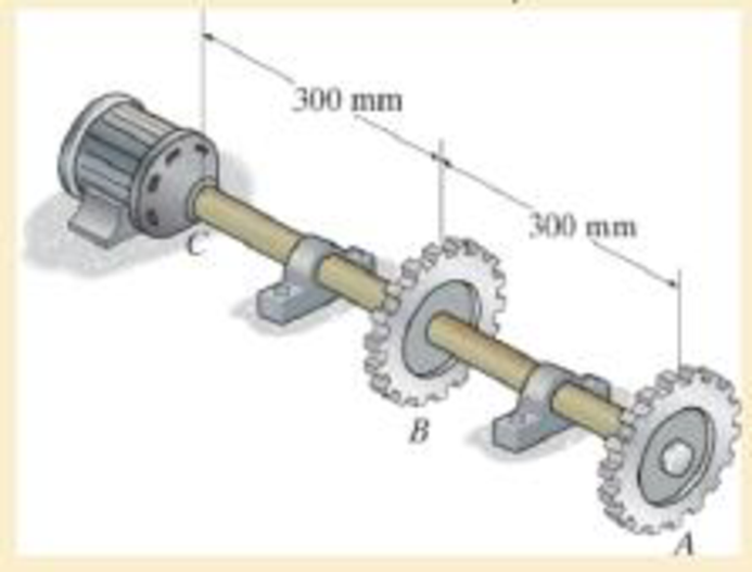
The required minimum diameter of the shaft.
The angle of twist of gear A relative to gear C.
Answer to Problem 5.1RP
The required minimum diameter of the shaft is
The angle of twist of gear A relative to gear C is
Explanation of Solution
Given information:
The allowable shear stress in the shaft is 75 MPa.
The motor supplies power of 8 kW.
Gear A and B withdraws power of 5 kW and 3 kW.
Shaft rotates at 300 rpm.
Calculation:
The expression for the power transmitted
Here, T is the applied torque and
Rearrange Equation (1) to find the torque at A.
Here,
The expression for angular velocity of the shaft
Here, f is the frequency of shaft’s rotation.
Substitute
Substitute 5 kW for
Find the torque at C.
Here,
Substitute 8 kW for
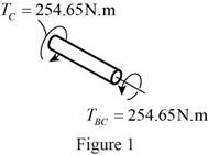
Sketch the internal torque in the segment BC of the shaft as shown in Figure 1.
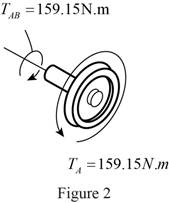
Sketch the internal torque in the segment AB of the shaft as shown in Figure 2.
Refer Figure 1 and Figure 2.
Segment BC of the shat is subjected to a greater internal torque of
The torsion formula for allowable maximum shear stress in the solid shaft
Here,
The outer radius of the shaft is r.
The polar moment of inertia for a solid shaft of radius
Substitute r for c and
Substitute 75 MPa for
The diameter of the shaft is twice the radius of the shaft. So the value of diameter is 26 mm.
Therefore, the required minimum diameter of the shaft is
Determine the angle of twist
Here, L is the length of the shaft and G is the shear modulus of elasticity of the material.
Rearrange Equation (7) for angle of twist of gear A relative to gear C
Refer the properties of A992 steel.
The value of shear modulus of elasticity of A992 steel is 75 GPa.
The value of radius of the solid shaft is 13 mm.
Substitute
Refer Figure 2.
The torque in the region AB of the shaft is
Refer Figure 1.
The torque in the region BC of the shaft is
Substitute
Therefore, the angle of twist of gear A relative to gear C is
Want to see more full solutions like this?
Chapter 5 Solutions
Mechanics of Materials (10th Edition)


- An office building is planned with a lateral-force-resisting system designed for earthquake resistance in aseismic zone. The seismic capacity of the proposed system, expressed as a force factor, is assumed tofollow a lognormal distribution with a median of 6.5 and a standard deviation of 1.5. The ground motionfrom the largest expected earthquake at the site is estimated to correspond to an equivalent force factor of 5.5.(a) What is the estimated probability that the building will experience damage when subjected to the largest expected earthquake? (b) If the building survives (i.e., experiences no damage) during a previous moderate earthquake with aforce factor of 4.0, what is the updated probability of failure of the building under the largest expectedearthquake?(c) Suppose future occurrences of the largest expected earthquake follow a Poisson process with a mean return period of 500 years. Assuming that damage events from different earthquakes are statisticallyindependent,…arrow_forwardDuring a plant visit, it was noticed that a 12-m-long section of a 10-cm-diameter steam pipe is completely exposed to the ambient air. The temperature measurements indicate that the average temperature of the outer surface of the steam pipe is 75°C when the ambient temperature is 5°C. There are also light winds in the area at 10 km/h. The emissivity of the outer surface of the pipe is 0.8, and the average temperature of the surfaces surrounding the pipe, including the sky, is estimated to be 0°C. Determine the amount of heat lost from the steam during a 10-h-long work day. Steam is supplied by a gas-fired steam generator that has an efficiency of 80 percent, and the plant pays $1.05/therm of natural gas. If the pipe is insulated and 90 percent of the heat loss is saved, determine the amount of money this facility will save a year as a result of insulating the steam pipes. Assume the plant operates every day of the year for 10 h. State your assumptions.arrow_forwardAn old fashioned ice cream kit consists of two concentric cylinders of radii Ra and Rb. The inner cylinder is filled with milk and ice cream ingredients while the space between the two cylinders is filled with an ice-brine mixture. Ice cream begins to form on the inner surface of the inner cylinder. To expedite the process, would you recommend rotating the inner cylinder? Justify your recommendation. icecream/ ice-brine Ra Rbarrow_forward
- Find temperatures STRICTLY USING RITZ APPROXIMATION METHODarrow_forwardSolve this Problem using RITZ APPROXIMATION. STEP BY STEParrow_forwardB/40 The body is constructed of a uniform square plate, a uniform straight rod, a uniform quarter‐circular rod, and a particle (negligible dimensions). If each part has the indicated mass, determine the mass moments of inertia of the body about the x‐, y‐, and z‐axes. Answer Given.arrow_forward
- (read image) Answer:arrow_forward(read image) Answer Givenarrow_forwardB/16. The plane area shown in the top portion of the figure is rotated 180° about the x‐axis to form the body of revolution of mass m shown in the lower portion of the figure. Determine the mass moment of inertia of the body about the x‐axis. Answer Givenarrow_forward
- (read image) Answer:arrow_forward(read image) Answer:arrow_forward2nd Law of Thermodynamics A 1.5-ft3 rigid tank contains saturated refrigerant-134 at 170 psia. Initially, 20 percent of the volume isoccupied by liquid and the rest by vapor. A valve at the top of the tank is now opened, and vapor is allowedto escape slowly from the tank. Heat is transferred to the refrigerant such that the pressure inside the tankremains constant. The valve is closed when the last drop of liquid in the tank is vaporized. Determine thetotal heat transfer for this process.arrow_forward
 Elements Of ElectromagneticsMechanical EngineeringISBN:9780190698614Author:Sadiku, Matthew N. O.Publisher:Oxford University Press
 Mechanics of Materials (10th Edition)Mechanical EngineeringISBN:9780134319650Author:Russell C. HibbelerPublisher:PEARSON
 Thermodynamics: An Engineering ApproachMechanical EngineeringISBN:9781259822674Author:Yunus A. Cengel Dr., Michael A. BolesPublisher:McGraw-Hill Education
 Control Systems EngineeringMechanical EngineeringISBN:9781118170519Author:Norman S. NisePublisher:WILEY
 Mechanics of Materials (MindTap Course List)Mechanical EngineeringISBN:9781337093347Author:Barry J. Goodno, James M. GerePublisher:Cengage Learning
 Engineering Mechanics: StaticsMechanical EngineeringISBN:9781118807330Author:James L. Meriam, L. G. Kraige, J. N. BoltonPublisher:WILEY