
Electronics Fundamentals: Circuits, Devices & Applications
8th Edition
ISBN: 9780135072950
Author: Thomas L. Floyd, David Buchla
Publisher: Prentice Hall
expand_more
expand_more
format_list_bulleted
Concept explainers
Videos
Textbook Question
Chapter 5, Problem 43P
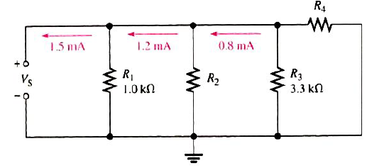
Determine the unknown resistances in Figure 5-79.
Expert Solution & Answer
Want to see the full answer?
Check out a sample textbook solution
Students have asked these similar questions
Q5B. Find the type of the controller in the following figures and use real values to find the transfer
function of three of them[ Hint Pi,Pd and Lead,lag are found so put the controller with its
corresponding compensator].
R₁
R₂
Rz
HE
C2
RA
HE
R₁
R2
RA
と
Q1// Sketch the root locus for the unity feedback system. Where
G(s)=)=
K
S3+252 +25
and find the following
a. Sketch the asymptotes
b. The exact point and gain where the locus crosses the jo-axis
c. The breakaway point on the real axis
d. The range of K within which the system is stable
e. Angles of departure and arrival.
Determine X(w) for the given function shown in Figure (1) by applying the
differentiation property of the Fourier Transform.
Figure (1)
-1
x(t)
Chapter 5 Solutions
Electronics Fundamentals: Circuits, Devices & Applications
Ch. 5 - Prob. 1TFQCh. 5 - The total resistance of parallel resistors is...Ch. 5 - The product-over-sum rule works for any number of...Ch. 5 - In a parallel circuit, the voltage is larger on a...Ch. 5 - Prob. 5TFQCh. 5 - Prob. 6TFQCh. 5 - Prob. 7TFQCh. 5 - In the current-divider formula, Ix=(RT/Rx)lT, the...Ch. 5 - Prob. 9TFQCh. 5 - The total power dissipated by parallel resistors...
Ch. 5 - In a parallel circuit, each resistor has the same...Ch. 5 - When a 1.2k resistor and a 100 resistor are...Ch. 5 - Prob. 3STCh. 5 - Eight resistors are in parallel. The two...Ch. 5 - When an additional resistor is connected across an...Ch. 5 - If one of the resistors in a parallel circuit is...Ch. 5 - The currents into a node are along two paths. One...Ch. 5 - Prob. 8STCh. 5 - Prob. 9STCh. 5 - Prob. 10STCh. 5 - In a certain three-branch parallel circuit,...Ch. 5 - Prob. 12STCh. 5 - Prob. 13STCh. 5 - Prob. 14STCh. 5 - Determine the cause for each set of symptoms....Ch. 5 - Prob. 2TSCCh. 5 - Prob. 3TSCCh. 5 - Prob. 4TSCCh. 5 - Determine the cause for each set of symptoms....Ch. 5 - Connect the resistors in Figure 5-57 in parallel...Ch. 5 - Determine whether or not all the resistors in...Ch. 5 - Determine the total resistance between pins 1 and...Ch. 5 - The following resistors are connected in parallel:...Ch. 5 - Find the total resistance between nodes A and B...Ch. 5 - Calculate RT for each circuit in Figure 5-60.Ch. 5 - What is the total resistance of eleven 22k...Ch. 5 - Five 15, ten 100, and two 10 resistors are all...Ch. 5 - Determine the voltage across and the current...Ch. 5 - The source voltage in Figure 5-61 is 100 V. How...Ch. 5 - Prob. 11PCh. 5 - The resistance of a 60 W bulb is approximatey 240....Ch. 5 - What is the current in each resistor for the...Ch. 5 - Four equal-value resistors are connected in...Ch. 5 - The following currents are measured in the same...Ch. 5 - There is a total of 500mA of current into five...Ch. 5 - How much current is through R2 and R3 in Figure...Ch. 5 - A trailer has four running lights that draw 0.5A...Ch. 5 - Assume the trailer in Problem 18 has two brake...Ch. 5 - A 10k resistor and a 15k resistor are in parallel...Ch. 5 - How much branch current should each meter in...Ch. 5 - Prob. 22PCh. 5 - Five parallel resistors each handle 40mW. What is...Ch. 5 - Prob. 24PCh. 5 - Six light bulbs are connected in parallel across...Ch. 5 - If one of the bulbs burns out in Problem 25, how...Ch. 5 - In Figure 5-67, the current and voltage...Ch. 5 - Prob. 28PCh. 5 - Find the open resistor in Figure 5-69.Ch. 5 - From the ohmmeter reading in Figure 5-70, can you...Ch. 5 - In the circuit of Figure 5-71, determine...Ch. 5 - The total resistance of a parallel circuit is 25....Ch. 5 - What is the current through each resistor in...Ch. 5 - A certain parallel circuit consists of only 12W...Ch. 5 - Find the values of the unspecified quantities...Ch. 5 - What is the total resistance between terminal A...Ch. 5 - What value of R2 in Figure 5-75 will cause...Ch. 5 - Determine the total current from the source and...Ch. 5 - The electrical circuit in a room is protected with...Ch. 5 - The total resistance of a parallel circuit is 25....Ch. 5 - Prob. 41PCh. 5 - If the total resistance in Figure 5-78 is 200,...Ch. 5 - Determine the unknown resistances in Figure 5-79.Ch. 5 - There is a total of 250 mA into a parallel circuit...Ch. 5 - Prob. 45PCh. 5 - Develop a test procedure to check the circuit in...Ch. 5 - A certain parallel circuit consists of five 12W...Ch. 5 - For the circuit board shown in Figure 5-82,...Ch. 5 - For the circuit board shown in Figure 5-82,...Ch. 5 - Open file P05-50; files are found at...Ch. 5 - Open file P05-51. Using current measurements,...Ch. 5 - Open file P05-52. Using current measurements,...
Knowledge Booster


Learn more about
Need a deep-dive on the concept behind this application? Look no further. Learn more about this topic, electrical-engineering and related others by exploring similar questions and additional content below.Similar questions
- Can you solve a question with a drawing Determine X(w) for the given function shown in Figure (1) by applying the differentiation property of the Fourier Transform. Figure (1) -1 x(t)arrow_forwardAn inductor has a current flow of 3 A when connected to a 240 V, 60 Hz power line. The inductor has a wire resistance of 15 Find the Q of the inductorarrow_forwardصورة من s94850121arrow_forward
- The joint density function of two continuous random variables X and Yis: p(x, y) = {Keós (x + y) Find (i) the constant K 0 2 0arrow_forwardShow all the steps please, Solve for the current through R2 if E2 is replaced by a current source of 10mA using superposition theorem. R5=470Ω R2=1000Ω R6=820Ωarrow_forwardPlease solve it by explaining the steps. I am trying to prepare for my exam tomorrow, so any tips and tricks to solve similar problems are highly appreciated. Plus, this is a past exam I am using to prepare.arrow_forwardPlease solve it by explaining the steps. I am trying to prepare for my exam today, so any tips and tricks to solve similar problems are highly appreciated. Plus, this is a past exam I am using to prepare.arrow_forwardIf C is the circle |z|=4 evaluate f f (z)dz for each of the following functions using residue. 1 f(z) = z(z²+6z+4)arrow_forwardIf C is the circle |z|=4 evaluate ff(z)dz for each of the following functions using residue. f(z) z(z²+6z+4)arrow_forwardDetermine X(w) for the given function shown in Figure (1) by applying the differentiation property of the Fourier Transform. 1 x(t) Figure (1) -2 I -1 1 2arrow_forwardPlease solve it by explaining the steps. I am trying to prepare for my exam tomorrow, so any tips and tricks to solve similar problems are highly appreciated. Plus, this is a past exam I am using to prepare.arrow_forwardPlease solve it by explaining the steps. I am trying to prepare for my exam tomorrow, so any tips and tricks to solve similar problems are highly appreciated. Plus, this is a past exam I am using to prepare.arrow_forwardarrow_back_iosSEE MORE QUESTIONSarrow_forward_ios
Recommended textbooks for you
 Electricity for Refrigeration, Heating, and Air C...Mechanical EngineeringISBN:9781337399128Author:Russell E. SmithPublisher:Cengage Learning
 Delmar's Standard Textbook Of ElectricityElectrical EngineeringISBN:9781337900348Author:Stephen L. HermanPublisher:Cengage Learning
Electricity for Refrigeration, Heating, and Air C...
Mechanical Engineering
ISBN:9781337399128
Author:Russell E. Smith
Publisher:Cengage Learning
Delmar's Standard Textbook Of Electricity
Electrical Engineering
ISBN:9781337900348
Author:Stephen L. Herman
Publisher:Cengage Learning
Electrical Measuring Instruments - Testing Equipment Electrical - Types of Electrical Meters; Author: Learning Engineering;https://www.youtube.com/watch?v=gkeJzRrwe5k;License: Standard YouTube License, CC-BY
01 - Instantaneous Power in AC Circuit Analysis (Electrical Engineering); Author: Math and Science;https://www.youtube.com/watch?v=If25y4Nhvw4;License: Standard YouTube License, CC-BY