
EBK PRINCIPLES OF ELECTRIC CIRCUITS
10th Edition
ISBN: 9780134879499
Author: Buchla
Publisher: YUZU
expand_more
expand_more
format_list_bulleted
Concept explainers
Videos
Textbook Question
Chapter 5, Problem 37P
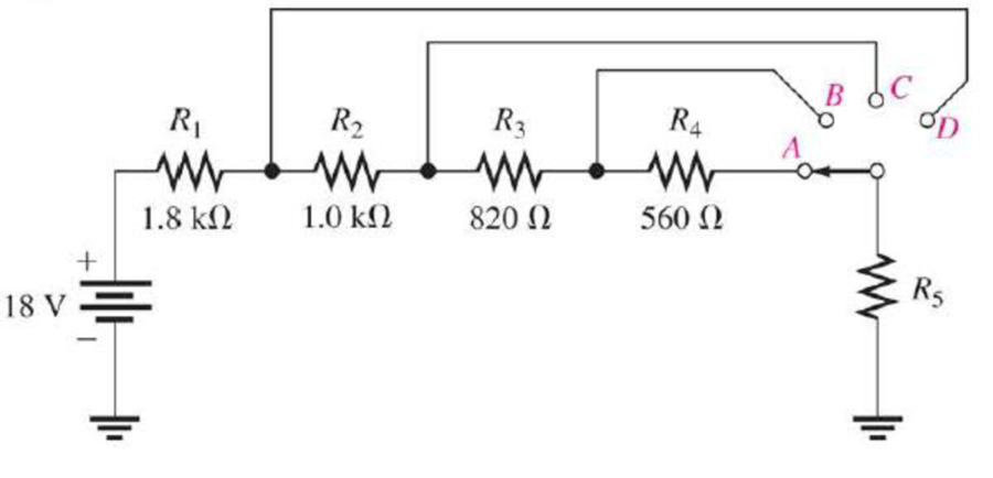
Determine the voltage across R5 for each position of the switch in Figure 5–81. The current in each position is as follows: A, 3.35 mA; B, 3.73 mA; C, 4.50 mA; D, 6.00 mA.
Figure 5–81
Expert Solution & Answer
Want to see the full answer?
Check out a sample textbook solution
Students have asked these similar questions
I need help in creating a matlab code to find the currents USING MARTIXS AND INVERSE to find the current
Problem 3
(a) Consider
x[n]
=
{
0,
1, 0 ≤ n ≤N-1
otherwise
_and_h[n] = {
1, 0 ≤ n ≤M-1
0, otherwise
with N > M. Plot the sequence y[n] = x[n] × h[n]. Make sure to specify the amplitude values
*
and time indices n of y[n] where y[n] is constant.
(b) Express the number L of samples of y[n] that are non-zero in terms of M and N.
(c) Consider
x'[n]
=
{
0,
1, N₁ ≤ n ≤ N₂
otherwise
1, M₁n M₂
and h'[n] =
=
0, otherwise
',
and assume that №2 - N₁ = N-1 and M2 - M₁
=
x'[n] h'[n] is equal to a shifted version of y[n]. What is the value of the shift?
-
= M 1. Show that the sequence y'[n]
=
Home Work
Calculate I, and I2 in the two-port of Fig. below
20
211=602
2/30° V
V₁
%12=-142
721=-j4 2
Z22=82
+
V₂
94
Chapter 5 Solutions
EBK PRINCIPLES OF ELECTRIC CIRCUITS
Ch. 5 - (a) Show how you would rewire the protoboard in...Ch. 5 - How is the circuit changed when pin 2 and pin 3 in...Ch. 5 - Determine the total resistance in Figure 5-10(a)...Ch. 5 - What is the total resistance for the following...Ch. 5 - Determine the value of R4 in Figure 5-12 if the...Ch. 5 - Find RT for three 1.0 k resistors and two 720 ...Ch. 5 - What is the value of R2 if the highest current is...Ch. 5 - Determine V3 if the polarity of VS2 is reversed in...Ch. 5 - Starting with Equation 5-5, prove that the...Ch. 5 - What is the power in the circuit of Figure 5-48 if...
Ch. 5 - Determine the minimum power rating required for...Ch. 5 - Assume that R1 is shorted In Figure 5-61. What...Ch. 5 - A series circuit can have more than one path for...Ch. 5 - The total resistance of a series circuit can be...Ch. 5 - If two series resistors are different sizes, the...Ch. 5 - If two series resistors are different sizes, the...Ch. 5 - If three equal resistors are used in a voltage...Ch. 5 - There is no valid electrical reason for installing...Ch. 5 - Kirchhoffs voltage law is valid only if a loop...Ch. 5 - Prob. 8TFQCh. 5 - Prob. 9TFQCh. 5 - If point A in a circuit has a voltage of +10 V and...Ch. 5 - Two equal-value resistors are connected in series...Ch. 5 - Prob. 2STCh. 5 - Prob. 3STCh. 5 - When one of four series resistors is removed from...Ch. 5 - Prob. 5STCh. 5 - A 9 V battery is connected across a series...Ch. 5 - While putting four 1.5 V batteries in a four-cell...Ch. 5 - If you measure all the voltage drops and the...Ch. 5 - There are six resistors in a given series circuit...Ch. 5 - A series circuit consists of a 4.7 k, a 5.6 k, and...Ch. 5 - Which of the following series combinations...Ch. 5 - The total power in a certain circuit is 1 W. Each...Ch. 5 - When you connect an ammeter in a series-resistive...Ch. 5 - While checking out a series-resistive circuit, you...Ch. 5 - With a 10 V voltage source connected between...Ch. 5 - For the conditions described in Question 1, the...Ch. 5 - When the switches are in position 1 and a short...Ch. 5 - When the switches are in position 2 and a short...Ch. 5 - If the current shown by one of the milliammeters...Ch. 5 - If the source voltage decreases, the current...Ch. 5 - If the current through R1 increases as a result of...Ch. 5 - If the switch is thrown from position A to...Ch. 5 - If the switch is thrown from position B to...Ch. 5 - If the switch is thrown from position C to...Ch. 5 - If R1 is changed to 1.2 k, the voltage from A to B...Ch. 5 - If R2 and R3 are interchanged, the voltage from A...Ch. 5 - If the source voltage increases from 8 V to 10 V,...Ch. 5 - Connect each set of resistors in Figure 563 in...Ch. 5 - Determine the groupings of resistors in Figure 564...Ch. 5 - Determine the nominal resistance between pins 1...Ch. 5 - Determine the nominal resistance between pins 2...Ch. 5 - On the double-sided PC board in Figure 565,...Ch. 5 - Prob. 6PCh. 5 - Prob. 7PCh. 5 - Calculate RT for each circuit of Figure 566....Ch. 5 - What is the total resistance of twelve 5.6 k...Ch. 5 - Six 56 resistors, eight 100 resistors, and two...Ch. 5 - Prob. 11PCh. 5 - You have the following resistor values available...Ch. 5 - Find the total resistance in Figure 566 if all...Ch. 5 - What is the total resistance from A to B for each...Ch. 5 - What is the current through each resistor in a...Ch. 5 - The current from the source in Figure 569 is 5 mA....Ch. 5 - Show how to connect a voltage source and an...Ch. 5 - Using 1.5 V batteries, a switch, and three lamps,...Ch. 5 - What is the current in each circuit of Figure 570?...Ch. 5 - Determine the voltage drop across each resistor in...Ch. 5 - Three 470 resistors are connected in series with...Ch. 5 - Four equal-value resistors are in series with a 5...Ch. 5 - What is the value of each resistor in Figure 571?...Ch. 5 - Determine VR1, R2, and R3 in Figure 5-72. Figure...Ch. 5 - For the circuit in Figure 573 the meter reads 7.84...Ch. 5 - Determine the current measured by the meter in...Ch. 5 - Refer to Figure 5-75. Assume the green LED drops...Ch. 5 - Refer to Figure 5-76. Assume there is a 2.0 V drop...Ch. 5 - Series aiding is a term sometimes used to describe...Ch. 5 - The term series opposing means that sources are in...Ch. 5 - Determine the total source voltage in each circuit...Ch. 5 - Prob. 32PCh. 5 - Five resistors are in series with a 20 V source....Ch. 5 - Determine the unspecified voltage drop(s) in each...Ch. 5 - In the circuit of Figure 5-79, determine the...Ch. 5 - Find R1, R2, and R3 in Figure 580. Figure 580Ch. 5 - Determine the voltage across R5 for each position...Ch. 5 - The total resistance of a circuit is 560 . What...Ch. 5 - Determine the voltage between points A and B in...Ch. 5 - Determine the voltage with respect to ground for...Ch. 5 - Determine the minimum and maximum voltage from the...Ch. 5 - What is the voltage across each resistor in Figure...Ch. 5 - Prob. 44PCh. 5 - If there are 10 V across R1 in Figure 5-86, what...Ch. 5 - Prob. 46PCh. 5 - Prob. 47PCh. 5 - Five series resistors each handle 50 mW. What is...Ch. 5 - If you double the voltage across a resistor, by...Ch. 5 - If the total resistance of a circuit is halved,...Ch. 5 - What is the total power in the circuit in Figure...Ch. 5 - The following W resistors are in series: 1.2 k,...Ch. 5 - Find RT in Figure 587.Ch. 5 - A certain series circuit consists of a W...Ch. 5 - Determine the voltage at each point with respect...Ch. 5 - In Figure 589, how would you determine the voltage...Ch. 5 - Determine the voltage at each point with respect...Ch. 5 - In Figure 589, what is VAC?Ch. 5 - In Figure 589, what is VCA?Ch. 5 - A string of five series resistors is connected...Ch. 5 - By observing the meters in Figure 590, determine...Ch. 5 - What current would you measure in Figure 590(b) if...Ch. 5 - Table 52 shows the results of resistance...Ch. 5 - You measure 15 k between pins 5 and 6 on the PC...Ch. 5 - In checking out the PC board in Figure 591, you...Ch. 5 - The three groups of series resistors on the PC...
Knowledge Booster


Learn more about
Need a deep-dive on the concept behind this application? Look no further. Learn more about this topic, electrical-engineering and related others by exploring similar questions and additional content below.Similar questions
- HW-2: Consider the loop of Figure below. If B = 0.5az Wb/m2, R = 20 2, e = 10 cm, and the rod is moving with a constant velocity of 8ax m/s, find (a) The induced emf in the rod (b) The current through the resistor y I 00 121 & B (in) 60 Answer: (a) 0.4 V, (b) 20 mA &arrow_forwardWrite a Verilog program to design the 4-bit ripple carry counter using the instantiation process available in Verilog HDL and write the stimulus program to check the functionality of the design. Assume 4-bit ripple carry counter is designed from a T-flipflop and T-flipflop is designed from a D- flipflop.arrow_forwardHW3: A 9.375-GHz uniform plane wave is propagating in polyethylene (&-2.26). If the amplitude of the electric field intensity is 500 V/m and the material is assumed to be lossless, find: (a) the phase constant; (b) thearrow_forward
- HW1: The location of the sliding bar in Figure below is given by x = 5t + 2t³, and the separation of the two rails is 20 cm. Let B = 0.8x2a, T. Find the voltmeter reading at (a) t = 0.4 s; (b) x = 0.6 m.arrow_forwardFor the circuit shown in Fig. 2.18, he =1.1 K2, hfe =50. Find Avf, Rif and Rof. { Ans: -3.2; 1935; X2807. Ans:-3-2;193;728. Vcc Rs=10kQ RF = 40kQ Re=4KQ -ov Vsarrow_forwardFor the system shown in figure below, the per unit values of different quantities are E-1.2, V 1, X X2-0.4. Xa-0.2 Determine whether the system is stable for a sustained fault. The fault is cleared at 8-60°. Is the system stable? If so find the maximum rotor swing. Find the critical clearing angle. E25 G X'd 08 CB X2 F CB V28 Infinite busarrow_forward
- 17 For the circuit shown in Fig. 2.20, the transistors are identical and have the following parameters: hfe = 50, hie 1.1K, hre = 0, and hoe = 0. Calculate Auf, Rif and Rof. 25 V {Ans #45.4; 112 KM; 129 150k 47k www www +11 www 10k 6 4.7k 50μF Rif R₂1000 w 4.7k 47k Vo Q2 33k 4.7k ww 50µF 5μF 4.7k 1 R₁ Rofarrow_forwardFor the circuit shown in Fig. 2.18, he =1.1 K2, hfe =50. Find Avf, Rif and Rof. { Ans: -3.2; 1935; X2807. Ans:-3-2;193;728. Vcc Rs=10kQ RF = 40kQ Re=4KQ -ov Vs Fig. 2.18 Circuit for Q5.arrow_forwardThe circuit of Fig. 2.16 is to have Af=-1mA/V, D=1+ BA = 50, a voltage gain of -4, Rs =1KQ, and hfe = 150. Find RL, Re, Rif and Rof.. Vcc www RL OV Ans: 4 kor; 98053150 KS;∞. { An Re Fig. 2.16 Circuit for Q3.arrow_forward
- During the lab you will design and measure a differential amplifier, made with an opamp. inside generator R5 ww 500 V1 0.1Vpk 1kHz 0° R6 w 50Ω R1 ww 10ΚΩ VCC C1 balanced wire R3 w 15.0V signal+ 100nF U1A TL082CP ground 2 signal- R4 w C2 Question5: Calculate R3 and R4 for a 20dB. 100nF VEE -15.0V R2 ww 10ΚΩarrow_forwardnot use ai pleasearrow_forward3. Consider the system described by the transfer function Gp(s) polynomial controller to satisfy the below specifications: 1) The settling time is t = 1 second, 2) 0.1% peak overshoot, 3) and zero steady-state error for a ramp input. The sampling period is T = 0.01 second. 1 = Design a discrete-time s(s+5)*arrow_forward
arrow_back_ios
SEE MORE QUESTIONS
arrow_forward_ios
Recommended textbooks for you
 Delmar's Standard Textbook Of ElectricityElectrical EngineeringISBN:9781337900348Author:Stephen L. HermanPublisher:Cengage Learning
 Electricity for Refrigeration, Heating, and Air C...Mechanical EngineeringISBN:9781337399128Author:Russell E. SmithPublisher:Cengage Learning
Delmar's Standard Textbook Of Electricity
Electrical Engineering
ISBN:9781337900348
Author:Stephen L. Herman
Publisher:Cengage Learning
Electricity for Refrigeration, Heating, and Air C...
Mechanical Engineering
ISBN:9781337399128
Author:Russell E. Smith
Publisher:Cengage Learning
Current Divider Rule; Author: Neso Academy;https://www.youtube.com/watch?v=hRU1mKWUehY;License: Standard YouTube License, CC-BY