
Concept explainers
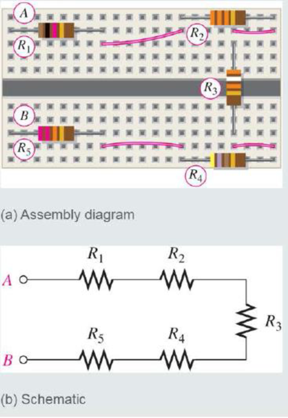
(a) Show how you would rewire the protoboard in Figure 5-4(a) so that all the odd-numbered resistors come first followed by the even-numbered ones. (b) Determine the resistance value of each resistor.
FIGURE 5-4
(a)
Show the rewired diagram of the protoboard in given Figure so that all the odd-numbered resistors come first followed by the even-numbered ones.
Explanation of Solution
Discussion:
Refer to given Figure 5-4 in the textbook.
The circuit in given Figure is redrawn as Figure 1 as per the given data.
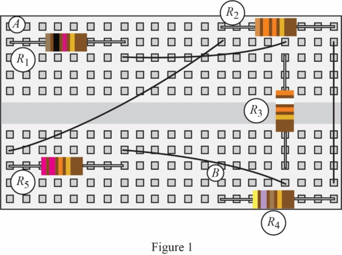
Given that, the odd-numbered resistors are connected first, and then followed by the even-numbered resistors. That is, the resistors
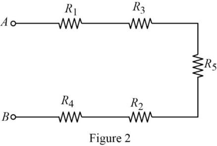
The schematic circuit of Figure 1 is drawn as Figure 2.
Conclusion:
Thus, the rewired diagram of the given protoboard is drawn.
(b)
Find the resistance value for each of the resistors in the given Figure.
Answer to Problem 1RP
The resistance value for the resistor
Explanation of Solution
Calculation:
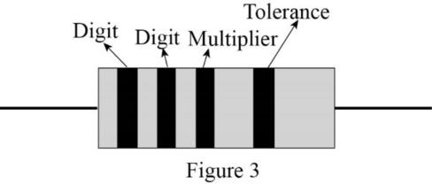
Using the standard color codes, the value of the resistors can be calculated. The resistor schematic with 4-band code is drawn as shown in Figure 3.
For Resistor
The color code for brown color is digit
Therefore, the value of the resistor
For Resistor
The color code for the first orange color line is digit
Therefore, the value of the resistor
For Resistor
The color code for orange color is digit
Therefore, the value of the resistor
For Resistor
The color code for yellow color is digit
Therefore, the value of the resistor
For Resistor
The color code for the first red color line is digit
Therefore, the value of the resistor
Conclusion:
Thus, the resistance value for the resistor
Want to see more full solutions like this?
Chapter 5 Solutions
EBK PRINCIPLES OF ELECTRIC CIRCUITS
Additional Engineering Textbook Solutions
Java How to Program, Early Objects (11th Edition) (Deitel: How to Program)
Java: An Introduction to Problem Solving and Programming (8th Edition)
Computer Science: An Overview (13th Edition) (What's New in Computer Science)
Starting Out With Visual Basic (8th Edition)
Modern Database Management
Starting Out with Java: From Control Structures through Objects (7th Edition) (What's New in Computer Science)


- EXAMPLE 8.12 The E-MOSFET of Fig. 8.40 was analyzed in Example 7.10, with the result that k = 0.24 × 10³ A/V², VGS = 6.4 V, and ID = 2.75 mA. a. Determine gm- b. Find rd. c. Calculate Z; with and without rd. Compare results. d. Find Zo with and without ra. Compare results. e. Find A, with and without rd. Compare results. 카 1 uF Z RE 912 V Rp • 2 ΚΩ 10 ΜΩ HE 1 μF ID (on) = 6 mA VGS (on) = 8 V VGS (Th) = 3 V 80s = 20 μs Za o Voarrow_forwardNO AI PLEASEarrow_forwardNO AI PLEASEarrow_forward
- I need handwritten solution to this, electrical engineering expert tutor s only,this is an assignment,I need 100% accuracyarrow_forward5. Determine the CT convolutions for the signals below. Sketch the signal that flips and on same plot the one that is not flipped. Do this for each overlap case. Clearly indicate all overlap cases and the integral limits. Finally, using the left squiggly bracket notation, show the output for each case versus time. (c) 4 x(t) 2 1 2(t) 4 x(t) 4 0123 et 20 x(t) (4) 4 (a) +(1) 24 T 0123 (b) T (f) 1 2-2 0123 (c) (f) 0123 (d) (1) A t 1(8) 4,121 -101 3 (e)arrow_forwardSolve by pen and paper not using chatgpt or AI Find the current io, and the voltage vo in the circuit in Figure 4. Answer: ἱο = 1.799 Α, νο = 17.99 V.arrow_forward
- "Hi Tutor, Please solve this question manually without using AI tools. AI solutions are often inaccurate in advanced electrical engineering. If you're unable to solve it manually, kindly let another qualified tutor assist me. I need reliable and accurate solutions. Thank you."arrow_forwardQ3: A conducting filamentary triangle joins points A(3, 1, 1), B(5, 4, 2), and C(1, 2, 4). The segment AB carries a current of 0.2 A in the аAB direction. There is present a magnetic field B = 0.2a, -0.1a,+ 0.3a, T. Find: (a) the force on segment BC; (b) the force on the triangular loop; (c) the torque on the loop about an origin at A; (d) the torque on the loop about an origin at C.arrow_forwardI want to find the current by using mesh analysis pleasearrow_forward
- Q2: Consider the rectangular loop shown in Figure below. Calculate the torque? Z 4 mA B, -0.6a,+0.8a, T (1, 2,0) Kamil Ans: 4.8a, mN.marrow_forwardQ4: A circular current loop of radius p and current I lies in the z = 0 plane. Find the Torque which results if the current is in the ag direction and there is a uniform field Ans: πp² Bol/√2 ay B = B₁ (ax+ay)/√2arrow_forwardQ1: A point charge for which Q = 2 x 10⁶ C is moving in the combined fields - E = 100ax 200a, +300a, V/m and B = -3ax + 2ay- az mT. If the charge velocity v = (2ax -3a, - 4a,) 105 m/s, find the unit vector showing the direction in which the charge is accelerating? Ans:.0.7ax +0.7a, -0.12a,arrow_forward
 Electricity for Refrigeration, Heating, and Air C...Mechanical EngineeringISBN:9781337399128Author:Russell E. SmithPublisher:Cengage Learning
 Delmar's Standard Textbook Of ElectricityElectrical EngineeringISBN:9781337900348Author:Stephen L. HermanPublisher:Cengage Learning