
EBK STATICS AND MECHANICS OF MATERIALS
5th Edition
ISBN: 8220102955295
Author: HIBBELER
Publisher: PEARSON
expand_more
expand_more
format_list_bulleted
Videos
Textbook Question
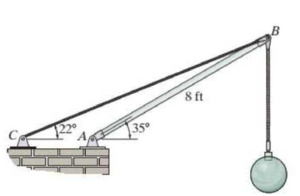
Chapter 4.4, Problem 7P
Determine the magnitude of force at the pin A and in the cable BC needed to support the 500-lb load. Neglect the weight of the boom AB.
Prob. 4-7
Expert Solution & Answer

Trending nowThis is a popular solution!

Students have asked these similar questions
(Read Question)
In figure A, the homogeneous rod of constant cross section is attached to unyielding supports. In figure B, a homogeneous bar with a cross-sectional area of 600 mm2 is attached to rigid supports. The bar carries the axial loads P1 = 20 kN and P2 = 60 kN, as shown.1. In figure A, derive the expression that calculates the reaction R1 in terms of P, and the given dimensions.2. In figure B, calculate the reaction (kN) at A.3. In figure B, calculate the maximum axial stress (MPa) in the rod.
(Read image)
Chapter 4 Solutions
EBK STATICS AND MECHANICS OF MATERIALS
Ch. 4.4 - Draw the free-body diagram of each object. Prob....Ch. 4.4 - Determine the horizontal and vertical components...Ch. 4.4 - Determine the horizontal and vertical components...Ch. 4.4 - The truss is supported by a pin at A and a roller...Ch. 4.4 - Determine the components of reaction at the fixed...Ch. 4.4 - The 25-kg bar has a center of mass at G. If it is...Ch. 4.4 - Determine the reactions at the smooth contact...Ch. 4.4 - Determine the components of the support reactions...Ch. 4.4 - Determine the reactions at the supports. Prob. 4-2Ch. 4.4 - Determine the horizontal and vertical components...
Ch. 4.4 - Determine the reactions at the supports. Prob. 4-4Ch. 4.4 - Determine the reactions at the supports. Prob. 4-5Ch. 4.4 - Determine the reactions at the supports. Prob. 4-6Ch. 4.4 - Determine the magnitude of force at the pin A and...Ch. 4.4 - The dimensions of a jib crane are given in the...Ch. 4.4 - The dimensions of a jib crane are given in the...Ch. 4.4 - The smooth pipe rests against the opening at the...Ch. 4.4 - The beam is horizontal and the springs are...Ch. 4.4 - The 10-kg uniform rod is pinned at end A. If it is...Ch. 4.4 - The man uses the hand truck to move material up...Ch. 4.4 - Three uniform books, each having a weight W and...Ch. 4.4 - Determine the reactions at the pin A and the...Ch. 4.4 - If rope BC will fail when the tension becomes 50...Ch. 4.4 - Prob. 17PCh. 4.4 - Prob. 18PCh. 4.4 - The cantilever footing is used to support a wall...Ch. 4.4 - Prob. 20PCh. 4.4 - A boy stands out at the end of the diving board,...Ch. 4.4 - Prob. 22PCh. 4.4 - Prob. 23PCh. 4.4 - Prob. 24PCh. 4.4 - Prob. 25PCh. 4.4 - The man attempts to pull the four wheeler up the...Ch. 4.6 - Draw the free-body diagram of each object.Ch. 4.6 - In each case, write the moment equations about the...Ch. 4.6 - Prob. 7FPCh. 4.6 - Prob. 8FPCh. 4.6 - The rod is supported by smooth journal bearings at...Ch. 4.6 - Determine the support reactions at the smooth...Ch. 4.6 - Determine the force developed in the short link...Ch. 4.6 - Determine the components of reaction that the...Ch. 4.6 - The uniform load has a mass of 600 kg and is...Ch. 4.6 - Due to an unequal distribution of fuel in the wing...Ch. 4.6 - Determine the components of reaction at the fixed...Ch. 4.6 - The 50-lb mulching machine has a center of gravity...Ch. 4.6 - Prob. 30PCh. 4.6 - The uniform concrete slab has a mass of 2400 kg....Ch. 4.6 - Prob. 32PCh. 4.6 - Determine the tension in each cable and the...Ch. 4.6 - The bent rod is supported at A, B, and C by smooth...Ch. 4.6 - Prob. 35PCh. 4.6 - The bar AB is supported by two smooth collars. At...Ch. 4.6 - The rod has a weight of 6 lb/ft. If it is...Ch. 4.6 - The sign has a mass of 100 kg with center of mass...Ch. 4.6 - Both pulleys cite fixed to the shaft and as the...Ch. 4.6 - Both pulleys are fixed to the shaft and as the...Ch. 4.6 - Prob. 41PCh. 4.8 - Determine the friction force at the surface of...Ch. 4.8 - Determine the couple moment M needed to cause...Ch. 4.8 - Prob. 6PPCh. 4.8 - Prob. 7PPCh. 4.8 - Prob. 13FPCh. 4.8 - Determine the minimum force P to prevent the 30-kg...Ch. 4.8 - Determine the maximum force P that can be applied...Ch. 4.8 - Prob. 16FPCh. 4.8 - Prob. 17FPCh. 4.8 - Prob. 18FPCh. 4.8 - Prob. 19FPCh. 4.8 - If the coefficient of static friction at all...Ch. 4.8 - Prob. 21FPCh. 4.8 - Prob. 42PCh. 4.8 - The tractor exerts a towing force T = 400 lb....Ch. 4.8 - The mine car and its contents have a total mass of...Ch. 4.8 - The winch on the truck is used to hoist the...Ch. 4.8 - Prob. 46PCh. 4.8 - The automobile has a mass of 2 Mg and center of...Ch. 4.8 - Prob. 48PCh. 4.8 - Prob. 49PCh. 4.8 - Prob. 50PCh. 4.8 - Determine the angle at which the applied force P...Ch. 4.8 - Prob. 52PCh. 4.8 - The 180-lb man climbs up the ladder and stops at...Ch. 4.8 - The 180-lb man climbs up the ladder and stops at...Ch. 4.8 - The spool of wire having a weight of 300 lb rests...Ch. 4.8 - The spool of wire having a weight of 300 lb rests...Ch. 4.8 - The ring has a mass of 0.5 kg and is resting on...Ch. 4.8 - Determine the smallest force P that must be...Ch. 4.8 - The man having a weight of 200 lb pushes...Ch. 4.8 - The uniform hoop of weight W is subjected to the...Ch. 4.8 - Prob. 61PCh. 4.8 - Prob. 62PCh. 4.8 - Prob. 63PCh. 4.8 - The coefficient of static Friction between the...Ch. 4 - If the roller at B can sustain a maximum load of 3...Ch. 4 - Determine the reactions at the supports A and B...Ch. 4 - Determine the normal reaction at the roller A and...Ch. 4 - Determine the horizontal and vertical components...Ch. 4 - Determine the x, y, z components of reaction at...Ch. 4 - Prob. 6RPCh. 4 - Prob. 7RPCh. 4 - The uniform 60-kg crate C rests uniformly on a...
Knowledge Booster


Learn more about
Need a deep-dive on the concept behind this application? Look no further. Learn more about this topic, mechanical-engineering and related others by exploring similar questions and additional content below.Similar questions
- (Read Image)arrow_forwardM16x2 grade 8.8 bolts No. 25 C1- Q.2. The figure is a cross section of a grade 25 cast-iron pressure vessel. A total of N, M16x2.0 grade 8.8 bolts are to be used to resist a separating force of 160 kN. (a) Determine ks, km, and C. (b) Find the number of bolts required for a load factor of 2 where the bolts may be reused when the joint 19 mm is taken apart. (c) with the number of bolts obtained in (b), determine the realized load factor for overload, the yielding factor of safety, and the separation factor of safety. 19 mmarrow_forwardProblem4. The thin uniform disk of mass m = 1-kg and radius R = 0.1m spins about the bent shaft OG with the angular speed w2 = 20 rad/s. At the same time, the shaft rotates about the z-axis with the angular speed 001 = 10 rad/s. The angle between the bent portion of the shaft and the z-axis is ẞ = 35°. The mass of the shaft is negligible compared to the mass of the disk. a. Find the angular momentum of the disk with respect to point G, based on the axis orientation as shown. Include an MVD in your solution. b. Find the angular momentum of the disk with respect to point O, based on the axis orientation as shown. (Note: O is NOT the center of fixed-point rotation.) c. Find the kinetic energy of the assembly. z R R 002 2R x Answer: H = -0.046ĵ-0.040 kg-m²/sec Ho=-0.146-0.015 kg-m²/sec T 0.518 N-m =arrow_forward
- Problem 3. The assembly shown consists of a solid sphere of mass m and the uniform slender rod of the same mass, both of which are welded to the shaft. The assembly is rotating with angular velocity w at a particular moment. Find the angular momentum with respect to point O, in terms of the axes shown. Answer: Ñ。 = ½mc²wcosßsinßĵ + (}{mr²w + 2mb²w + ½ mc²wcos²ß) k 3 m r b 2 C لا marrow_forwardOnly question 2arrow_forwardOnly question 1arrow_forward
- Only question 3arrow_forwardI have Euler parameters that describe the orientation of N relative to Q, e = -0.7071*n3, e4 = 0.7071. I have Euler parameters that describe the orientation of U relative to N, e = -1/sqrt(3)*n1, e4 = sqrt(2/3). After using euler parameter rule of successive rotations, I get euler parameters that describe the orientation of U relative to Q, e = -0.4082*n1 - 0.4082*n2 - 0.5774*n3. I need euler parameters that describe the orientation of U relative to Q in vector basis of q instead of n. How do I get that?arrow_forwardDescribe at least 4 processes in engineering where control charts are (or should be) appliedarrow_forward
- Describe at least two (2) processes where control charts are (or should be) applied.arrow_forwardProblem 3: A cube-shaped spacecraft is in a circular Earth orbit. Let N (n,) be inertial and the spacecraft is denoted S (ŝ₁). The spacecraft is described such that ¯½º = J ŝ₁ŝ₁ + J ŝ₂§₂ + J §¸Ŝ3 Location of the spacecraft in the orbit is determined by the orbit-fixed unit vectors ê, that are oriented by the angle (Qt), where is a constant angular rate. 52 €3 3> 2t 55 Λ Из At the instant when Qt = 90°, the spacecraft S is oriented relative to the orbit such that 8₁ = 0° Space-three 1-2-3 angles 0₂ = 60° and ES = $₂ rad/s 0₁ = 135° (a) At this instant, determine the direction cosine matrix that describes the orientation of the spacecraft with respect to the inertial frame N.arrow_forwardThis problem illustrates that the factor of safety for a machine element depends on the particular point selected for analysis. Here you are to compute factors of safety, based upon the distortion-energy theory, for stress elements at A and B of the member shown in the figure. This bar is made of AISI 1006 cold-drawn steel and is loaded by the forces F = 1.100 kN, P = 8.00 kN, and T = 50.00 N-m. Given: Sy = 280 MPa. B -100 mm- 15-mm D. a) Determine the value of the axial stress at point B. b) Determine the value of the shear stress at point B. c) Determine the value of the Von Mises stress at point B. P Farrow_forward
arrow_back_ios
SEE MORE QUESTIONS
arrow_forward_ios
Recommended textbooks for you
 International Edition---engineering Mechanics: St...Mechanical EngineeringISBN:9781305501607Author:Andrew Pytel And Jaan KiusalaasPublisher:CENGAGE L
International Edition---engineering Mechanics: St...
Mechanical Engineering
ISBN:9781305501607
Author:Andrew Pytel And Jaan Kiusalaas
Publisher:CENGAGE L
Physics 33 - Fluid Statics (1 of 10) Pressure in a Fluid; Author: Michel van Biezen;https://www.youtube.com/watch?v=mzjlAla3H1Q;License: Standard YouTube License, CC-BY