
Vector Mechanics for Engineers: Statics, 11th Edition
11th Edition
ISBN: 9780077687304
Author: Ferdinand P. Beer, E. Russell Johnston Jr., David Mazurek
Publisher: McGraw-Hill Education
expand_more
expand_more
format_list_bulleted
Concept explainers
Videos
Textbook Question
Chapter 4.3, Problem 4.119P
PROBLEM 4.119
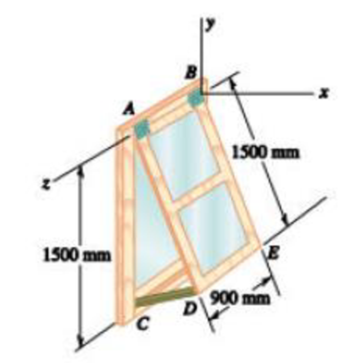
Solve Prob. 4.113, assuming that the hinge at A has been removed and that the hinge at B can exert couples about axes parallel to the x and y axes.
PROBLEM 4.113 A 10-kg storm window measuring 900 × 1500 mm is held by hinges at A and B. In the position shown, it is held away from the side of the house by a 600-mm stick CD. Assuming that the hinge at A does not exert any axial thrust, determine the magnitude of the force exerted by the stick and the components of the reactions at A and B.
Expert Solution & Answer
Want to see the full answer?
Check out a sample textbook solution
Students have asked these similar questions
M16x2 grade 8.8 bolts No. 25 C1-
Q.2. The figure is a cross section of a grade 25 cast-iron pressure vessel. A
total of N, M16x2.0 grade 8.8 bolts are to be used to resist a separating
force of 160 kN. (a) Determine ks, km, and C. (b) Find the number of bolts
required for a load factor of 2 where the bolts may be reused when the joint 19 mm
is taken apart. (c) with the number of bolts obtained in (b), determine the
realized load factor for overload, the yielding factor of safety, and the
separation factor of safety.
19 mm
Problem4.
The thin uniform disk of mass m = 1-kg and radius R = 0.1m spins about the bent shaft OG with
the angular speed w2 = 20 rad/s. At the same time, the shaft rotates about the z-axis with the angular
speed 001 = 10 rad/s. The angle between the bent portion of the shaft and the z-axis is ẞ = 35°. The
mass of the shaft is negligible compared to the mass of the disk.
a. Find the angular momentum of the disk with respect to point G, based on the axis
orientation as shown. Include an MVD in your solution.
b. Find the angular momentum of the disk with respect to point O, based on the axis
orientation as shown. (Note: O is NOT the center of fixed-point rotation.)
c. Find the kinetic energy of the assembly.
z
R
R
002
2R
x
Answer: H = -0.046ĵ-0.040 kg-m²/sec
Ho=-0.146-0.015 kg-m²/sec
T 0.518 N-m
=
Problem 3.
The assembly shown consists of a solid sphere of mass m and the uniform slender rod of the same
mass, both of which are welded to the shaft. The assembly is rotating with angular velocity w at a
particular moment. Find the angular momentum with respect to point O, in terms of the axes
shown.
Answer: Ñ。 = ½mc²wcosßsinßĵ + (}{mr²w + 2mb²w + ½ mc²wcos²ß) k
3
m
r
b
2
C
لا
m
Chapter 4 Solutions
Vector Mechanics for Engineers: Statics, 11th Edition
Ch. 4.1 - Two crates, each of mass 350 kg, are placed as...Ch. 4.1 - A lever AB is hinged at C and attached to a...Ch. 4.1 - A light rod AD is supported by frictionless pegs...Ch. 4.1 - A tension of 20 N is maintained in a tape as it...Ch. 4.1 - A gardener uses a 60 N wheelbarrow to transport a...Ch. 4.1 - The gardener of Prob. 4.1 wishes to transport a...Ch. 4.1 - A 2100-lb tractor is used to lift 900 lb of grave....Ch. 4.1 - For the beam and loading shown, determine (a) the...Ch. 4.1 - A load of lumber of weight W = 25 kN is being...Ch. 4.1 - A load of lumber of weight W = 25 kN is being...
Ch. 4.1 - 4.7 A T-shaped bracket supports the four loads...Ch. 4.1 - 4.8 For the bracket and loading of Prob. 4.7,...Ch. 4.1 - Three loads are applied as shown to a light beam...Ch. 4.1 - 4.10 Three loads are applied as shown to a light...Ch. 4.1 - 4.11 For the beam of Prob. 4.10, determine the...Ch. 4.1 - For the beam of Sample Prob. 4.2, determine the...Ch. 4.1 - The maximum allowable value of each of the...Ch. 4.1 - For the beam and loading shown, determine the...Ch. 4.1 - Prob. 4.15PCh. 4.1 - Prob. 4.16PCh. 4.1 - Prob. 4.17PCh. 4.1 - Prob. 4.18PCh. 4.1 - The bracket BCD is hinged at C and attached to a...Ch. 4.1 - The ladder AB, of length L and weight W, can be...Ch. 4.1 - 4.21 The 40-ft boom AB weighs 2 kips; the distance...Ch. 4.1 - A lever AB is hinged at C and attached to a...Ch. 4.1 - 4.23 and 4.24 For each of the plates and loadings...Ch. 4.1 - 4.23 and 4.24 For each of the plates and loadings...Ch. 4.1 - A rod AB, hinged at A and attached at B to cable...Ch. 4.1 - Fig. P4.25 and P4.26 4.26 A rod AB, hinged at A...Ch. 4.1 - Prob. 4.27PCh. 4.1 - Determine the reactions at A and C when (a) = 0,...Ch. 4.1 - Prob. 4.29PCh. 4.1 - Prob. 4.30PCh. 4.1 - Neglecting friction, determine the tension in...Ch. 4.1 - Fig. P4.31 and P4.32 4.32 Neglecting friction,...Ch. 4.1 - PROBLEM 4.33 A force P of magnitude 90 lb is...Ch. 4.1 - PROBLEM 4.34 Solve Problem 4,33 for a = 6 in,...Ch. 4.1 - Bar AC supports two 400-N loads as shown. Rollers...Ch. 4.1 - PROBLEM 4.36 A light bar AD is suspended from a...Ch. 4.1 - Prob. 4.37PCh. 4.1 - Prob. 4.38PCh. 4.1 - Prob. 4.39PCh. 4.1 - 4.40 A light bar AB supports a 15-kg block at its...Ch. 4.1 - 4.41 Two slots have been cut in plate DEF, and the...Ch. 4.1 - Prob. 4.42PCh. 4.1 - The rig shown consists of a 1200-lb horizontal...Ch. 4.1 - Fig. P4.43 4.44 For the rig and crate of Prob....Ch. 4.1 - A 175-kg utility pole is used to support at C the...Ch. 4.1 - Knowing that the tension in wire BD is 1300 N,...Ch. 4.1 - Fig. P4.46 and P4.47 4.47 Determine the range of...Ch. 4.1 - Beam AD carries the two 40-lb loads shown. The...Ch. 4.1 - Fig. P4.48 and P4.49 4.49 For the beam and loading...Ch. 4.1 - Prob. 4.50PCh. 4.1 - A uniform rod AB with a length of l and weight of...Ch. 4.1 - Rod AD is acted upon by a vertical force P at end...Ch. 4.1 - A slender rod AB with a weigh of W is attached to...Ch. 4.1 - 4.54 and 4.55 A vertical load P is applied at end...Ch. 4.1 - 4.54 and 4.55 A vertical load P is applied at end...Ch. 4.1 - A collar B with a weight of W can move freely...Ch. 4.1 - A 400-lb weight is attached at A to the lever...Ch. 4.1 - Prob. 4.58PCh. 4.1 - Eight identical 500 750-mm rectangular plates,...Ch. 4.1 - Prob. 4.60PCh. 4.2 - A 500-lb cylindrical tank, 8 ft in diameter, is to...Ch. 4.2 - 4.62.Determine the reactions at A and B when a =...Ch. 4.2 - Prob. 4.63PCh. 4.2 - Prob. 4.64PCh. 4.2 - Determine the reactions at B and C when a = 30 mm.Ch. 4.2 - Prob. 4.66PCh. 4.2 - Determine the reactions at B and D when b = 60 mm....Ch. 4.2 - For the frame and loading shown, determine the...Ch. 4.2 - A 50-kg crate is attached to the trolley-beam...Ch. 4.2 - One end of rod AB rests in the corner A and the...Ch. 4.2 - For the boom and loading shown, determine (a) the...Ch. 4.2 - Prob. 4.72PCh. 4.2 - Prob. 4.73PCh. 4.2 - Prob. 4.74PCh. 4.2 - Rod AB is supported by a pin and bracket at A and...Ch. 4.2 - Solve Prob. 4.75, assuming that the 170-N force...Ch. 4.2 - Prob. 4.77PCh. 4.2 - Using the method of Sec. 4.2B, solve Prob. 4.22....Ch. 4.2 - Knowing that = 30, determine the reaction (a) at...Ch. 4.2 - Prob. 4.80PCh. 4.2 - Determine the reactions at A and B when = 50....Ch. 4.2 - Determine the reactions at A and B when = 80.Ch. 4.2 - Rod AB is bent into the shape of an arc of circle...Ch. 4.2 - A slender rod of length L is attached to collars...Ch. 4.2 - Prob. 4.85PCh. 4.2 - Prob. 4.86PCh. 4.2 - A slender rod BC with a length of L and weight W...Ch. 4.2 - A thin ring with a mass of 2 kg and radius r = 140...Ch. 4.2 - Prob. 4.89PCh. 4.2 - Prob. 4.90PCh. 4.3 - Two tape spools are attached to an axle supported...Ch. 4.3 - A 12-m pole supports a horizontal cable CD and is...Ch. 4.3 - A 20-kg cover for a roof opening is hinged at...Ch. 4.3 - END-OF-SECTION PROBLEMS 4.91 Two transmission...Ch. 4.3 - Solve Prob. 4.91, assuming that the pulley rotates...Ch. 4.3 - A small winch is used to raise a 120-lb load. Find...Ch. 4.3 - 4.94 A 4 × 8-ft sheet of plywood weighing 34 lb...Ch. 4.3 - A 250 400-mm plate of mass 12 kg and a...Ch. 4.3 - Solve Prob. 4.95 for = 60. 4.95 A 250 400-mm...Ch. 4.3 - 4.97 The 20 × 20-in. square plate shown weighs 56...Ch. 4.3 - 4.98 The 20 × 20-in. square plate shows weighs 56...Ch. 4.3 - An opening in a floor is covered by a 1 1.2-m...Ch. 4.3 - PROBLEM 4.100 Solve Problem 4.99, assuming that...Ch. 4.3 - PROBLEM 4.101 Two steel pipes AB and BC, each...Ch. 4.3 - PROBLEM 4.102 For the pipe assembly of Problem...Ch. 4.3 - PROBLEM 4.103 The 24-lb square plate shown is...Ch. 4.3 - PROBLEM 4.104 The table shown weighs 30 lb and has...Ch. 4.3 - PROBLEM 4.105 A 10-ft boom is acted upon by the...Ch. 4.3 - PROBLEM 4.106 The 6-m pole ABC is acted upon by a...Ch. 4.3 - PROBLEM 4.107 Solve Problem 4.106 for a = 1.5 m....Ch. 4.3 - Prob. 4.108PCh. 4.3 - Prob. 4.109PCh. 4.3 - Prob. 4.110PCh. 4.3 - PROBLEM 4.111 A 48-in. boom is held by a...Ch. 4.3 - PROBLEM 4.112 Solve Problem 4.111, assuming that...Ch. 4.3 - PROBLEM 4.114 The bent rod ABEF is supported by...Ch. 4.3 - Prob. 4.114PCh. 4.3 - The horizontal platform ABCD weighs 60 lb and...Ch. 4.3 - PROBLEM 4.116 The lid of a roof scuttle weighs 75...Ch. 4.3 - PROBLEM 4.117 A 100-kg uniform rectangular plate...Ch. 4.3 - Solve Prob. 4.117, assuming that cable DCE is...Ch. 4.3 - PROBLEM 4.119 Solve Prob. 4.113, assuming that the...Ch. 4.3 - PROBLEM 4.120 Solve Prob. 4.115, assuming that the...Ch. 4.3 - PROBLEM 4.121 The assembly shown is used to...Ch. 4.3 - PROBLEM 4.122 The assembly shown is welded to...Ch. 4.3 - 4.123 The rigid L-shaped member ABC is supported...Ch. 4.3 - Prob. 4.124PCh. 4.3 - The rigid L-shaped member ABF is supported by a...Ch. 4.3 - Solve Prob. 4.125, assuming that the load at C has...Ch. 4.3 - Three rods are welded together to form a corner...Ch. 4.3 - Prob. 4.128PCh. 4.3 - Frame ABCD is supported by a ball-and-socket joint...Ch. 4.3 - Prob. 4.130PCh. 4.3 - Prob. 4.131PCh. 4.3 - PROBLEM 4.132 The uniform 10kg rod AB is supported...Ch. 4.3 - The frame ACD is supported by ball-and-socket...Ch. 4.3 - Solve Prob. 4.133, assuming that cable GBH is...Ch. 4.3 - Prob. 4.135PCh. 4.3 - Prob. 4.136PCh. 4.3 - Prob. 4.137PCh. 4.3 - The pipe ACDE is supported by ball-and-socket...Ch. 4.3 - Solve Prob. 4.138, assuming that wire DF is...Ch. 4.3 - Two 2 4-ft plywood panels, each with a weight of...Ch. 4.3 - Solve Prob. 4.140, subject to the restriction that...Ch. 4 - A 3200-lb forklift truck is used to lift a 1700-lb...Ch. 4 - The lever BCD is hinged at C and attached to a...Ch. 4 - Determine the reactions at A and B when (a) h =0,...Ch. 4 - Neglecting friction and the radius of the pulley,...Ch. 4 - PROBLEM 4.146 Bar AD is attached at A and C to...Ch. 4 - PROBLEM 4.147 A slender rod AB, of weight W, is...Ch. 4 - PROBLEM 4.148 Determine the reactions at A and B...Ch. 4 - For the frame and loading shown, determine the...Ch. 4 - PROBLEM 4.150 A 200-mm lever and a 240-mm-diameter...Ch. 4 - The 45-lb square plate shown is supported by three...Ch. 4 - The rectangular plate shown weighs 75 lb and is...Ch. 4 - A force P is applied to a bent rod ABC, which may...
Knowledge Booster


Learn more about
Need a deep-dive on the concept behind this application? Look no further. Learn more about this topic, mechanical-engineering and related others by exploring similar questions and additional content below.Similar questions
- I have Euler parameters that describe the orientation of N relative to Q, e = -0.7071*n3, e4 = 0.7071. I have Euler parameters that describe the orientation of U relative to N, e = -1/sqrt(3)*n1, e4 = sqrt(2/3). After using euler parameter rule of successive rotations, I get euler parameters that describe the orientation of U relative to Q, e = -0.4082*n1 - 0.4082*n2 - 0.5774*n3. I need euler parameters that describe the orientation of U relative to Q in vector basis of q instead of n. How do I get that?arrow_forwardDescribe at least 4 processes in engineering where control charts are (or should be) appliedarrow_forwardDescribe at least two (2) processes where control charts are (or should be) applied.arrow_forward
- Problem 3: A cube-shaped spacecraft is in a circular Earth orbit. Let N (n,) be inertial and the spacecraft is denoted S (ŝ₁). The spacecraft is described such that ¯½º = J ŝ₁ŝ₁ + J ŝ₂§₂ + J §¸Ŝ3 Location of the spacecraft in the orbit is determined by the orbit-fixed unit vectors ê, that are oriented by the angle (Qt), where is a constant angular rate. 52 €3 3> 2t 55 Λ Из At the instant when Qt = 90°, the spacecraft S is oriented relative to the orbit such that 8₁ = 0° Space-three 1-2-3 angles 0₂ = 60° and ES = $₂ rad/s 0₁ = 135° (a) At this instant, determine the direction cosine matrix that describes the orientation of the spacecraft with respect to the inertial frame N.arrow_forwardThis problem illustrates that the factor of safety for a machine element depends on the particular point selected for analysis. Here you are to compute factors of safety, based upon the distortion-energy theory, for stress elements at A and B of the member shown in the figure. This bar is made of AISI 1006 cold-drawn steel and is loaded by the forces F = 1.100 kN, P = 8.00 kN, and T = 50.00 N-m. Given: Sy = 280 MPa. B -100 mm- 15-mm D. a) Determine the value of the axial stress at point B. b) Determine the value of the shear stress at point B. c) Determine the value of the Von Mises stress at point B. P Farrow_forwardA piston-cylinder device initially contains 0.08 m^3 of nitrogen gas at 130 kPa and 170°C. The nitrogen is expanded to a pressure of 80 kPa via isentropic expansion. Determine the final temperature and the boundary work done by the system during this process.arrow_forward
- A Carnot (ideal) heat pump is to be used to heat a house and maintain it at 22°C in winter. On a day when the average outdoor temperature remains at about 0°C, the house is estimated to lose heat at a rate of 65,000 kJ/h. If the heat pump consumes 6 kW of power while operating, determine: (a) how long the heat pump ran on that day (b) the total heating costs, assuming an average price of 11¢/kWh for electricity (c) the heating cost for the same day if an 85% efficient electric furnace is used instead of a heat pump.arrow_forwardFrom the information in the image, I needed to find the orientation of U relative to Q in vector basis q_hat. I transformed the euler angle/axis representation to euler parameters. Then I got its conjugate in order to get the euler parameter in N frame relative to Q. The problem gave the euler angle/axis representation in Q frame relative to N, so I needed to find the conjugate. Then I used the euler parameter rule of successive rotation to find the final euler parameters that describe the orientation of U relative to Q. However that orientation is in n_hat which is the intermediate frame. How do I get the final result in q_hat?arrow_forwardA proposed method of power generation involves collecting and storing solar energy in large artificial lakes a few meters deep, called solar ponds. Solar energy is absorbed by all parts of the pond, and the water temperature rises everywhere. The top part of the pond, however, loses much of the heat it absorbs to the atmosphere, and as a result, the cool surface water serves as insulation for the bottom part of the pond and helps trap the energy there. Usually, salt is planted at the bottom of the pond to prevent the rise of this hot water to the top. A heat engine that uses an organic fluid, such as alcohol, as the working fluid can be operated between the top and the bottom portions of the pond. If the water temperature is 27°C near the surface and 72°C near the bottom of the pond, determine the maximum thermal efficiency that this power plant can have. Treat the cycle as an ideal heat engine. Would a heat engine operating under these temperature conditions (27°C and 72°C) be…arrow_forward
arrow_back_ios
SEE MORE QUESTIONS
arrow_forward_ios
Recommended textbooks for you
 Elements Of ElectromagneticsMechanical EngineeringISBN:9780190698614Author:Sadiku, Matthew N. O.Publisher:Oxford University Press
 Mechanics of Materials (10th Edition)Mechanical EngineeringISBN:9780134319650Author:Russell C. HibbelerPublisher:PEARSON
 Thermodynamics: An Engineering ApproachMechanical EngineeringISBN:9781259822674Author:Yunus A. Cengel Dr., Michael A. BolesPublisher:McGraw-Hill Education
 Control Systems EngineeringMechanical EngineeringISBN:9781118170519Author:Norman S. NisePublisher:WILEY
 Mechanics of Materials (MindTap Course List)Mechanical EngineeringISBN:9781337093347Author:Barry J. Goodno, James M. GerePublisher:Cengage Learning
 Engineering Mechanics: StaticsMechanical EngineeringISBN:9781118807330Author:James L. Meriam, L. G. Kraige, J. N. BoltonPublisher:WILEY
Elements Of Electromagnetics
Mechanical Engineering
ISBN:9780190698614
Author:Sadiku, Matthew N. O.
Publisher:Oxford University Press
Mechanics of Materials (10th Edition)
Mechanical Engineering
ISBN:9780134319650
Author:Russell C. Hibbeler
Publisher:PEARSON
Thermodynamics: An Engineering Approach
Mechanical Engineering
ISBN:9781259822674
Author:Yunus A. Cengel Dr., Michael A. Boles
Publisher:McGraw-Hill Education
Control Systems Engineering
Mechanical Engineering
ISBN:9781118170519
Author:Norman S. Nise
Publisher:WILEY
Mechanics of Materials (MindTap Course List)
Mechanical Engineering
ISBN:9781337093347
Author:Barry J. Goodno, James M. Gere
Publisher:Cengage Learning
Engineering Mechanics: Statics
Mechanical Engineering
ISBN:9781118807330
Author:James L. Meriam, L. G. Kraige, J. N. Bolton
Publisher:WILEY
Dynamics - Lesson 1: Introduction and Constant Acceleration Equations; Author: Jeff Hanson;https://www.youtube.com/watch?v=7aMiZ3b0Ieg;License: Standard YouTube License, CC-BY