
Concept explainers
Videos
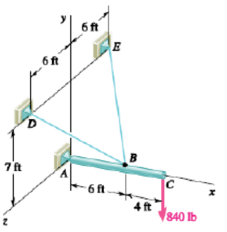
PROBLEM 4.105
A 10-ft boom is acted upon by the 840-lb force shown. Determine the tension in each cable and the reaction at the ball-and-socket joint at A.
The tension in each cable and the reaction at the ball and socket joint at A.
Answer to Problem 4.105P
The tension in cable BD is
Explanation of Solution
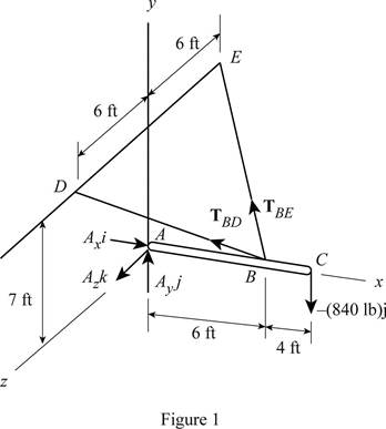
The free body diagram corresponding to the system of cable is shown in figure 1 plotted below.
A down ward force of magnitude
Write the equation to find the position vector
Here,
Write the equation to find the position vector
Here,
Write the equation to find the magnitude of
Here,
Write the equation to find the magnitude of
Here,
Write the equation to find the tension along cable BD.
Here,
Write the equation to find the tension along cable BE.
Here,
Write the equation to find the moments at point B due to force at D.
Here,
Write the equation to find the moment at point B due to force at point E.
Here,
Write the equation to find the moment of force at point B due to force at point C.
Here,
Write the equation to find the sum of moment of force at point B.
Here,
Substitute equation (VII), (VIII), and (IX) in equation (X) to find the
Substitute
Since sum of all external force acting on a body is zero, equate the equation for moments to zero.
Write the equation to find the sum of x components of force.
Write the equation to find the sum of y components of force.
Write the equation to find the sum of z component of forces.
Conclusion:
Substitute
Substitute
Substitute
Substitute
Substitute
Equate the coefficients of unit vectors
Equate the coefficient of unit vector
Equate the coefficients of unit vector
Substitute
Substitute
Substitute
Therefore, the tension in cable BD is
Want to see more full solutions like this?
Chapter 4 Solutions
Vector Mechanics for Engineers: Statics
Additional Engineering Textbook Solutions
Fluid Mechanics: Fundamentals and Applications
Automotive Technology: Principles, Diagnosis, And Service (6th Edition) (halderman Automotive Series)
Elementary Surveying: An Introduction To Geomatics (15th Edition)
Modern Database Management
Thinking Like an Engineer: An Active Learning Approach (4th Edition)
Vector Mechanics for Engineers: Statics and Dynamics


- In figure A, the homogeneous rod of constant cross section is attached to unyielding supports. In figure B, a homogeneous bar with a cross-sectional area of 600 mm2 is attached to rigid supports. The bar carries the axial loads P1 = 20 kN and P2 = 60 kN, as shown.1. In figure A, derive the expression that calculates the reaction R1 in terms of P, and the given dimensions.2. In figure B, calculate the reaction (kN) at A.3. In figure B, calculate the maximum axial stress (MPa) in the rod.arrow_forward(Read image)arrow_forward(Read Image)arrow_forward
- M16x2 grade 8.8 bolts No. 25 C1- Q.2. The figure is a cross section of a grade 25 cast-iron pressure vessel. A total of N, M16x2.0 grade 8.8 bolts are to be used to resist a separating force of 160 kN. (a) Determine ks, km, and C. (b) Find the number of bolts required for a load factor of 2 where the bolts may be reused when the joint 19 mm is taken apart. (c) with the number of bolts obtained in (b), determine the realized load factor for overload, the yielding factor of safety, and the separation factor of safety. 19 mmarrow_forwardProblem4. The thin uniform disk of mass m = 1-kg and radius R = 0.1m spins about the bent shaft OG with the angular speed w2 = 20 rad/s. At the same time, the shaft rotates about the z-axis with the angular speed 001 = 10 rad/s. The angle between the bent portion of the shaft and the z-axis is ẞ = 35°. The mass of the shaft is negligible compared to the mass of the disk. a. Find the angular momentum of the disk with respect to point G, based on the axis orientation as shown. Include an MVD in your solution. b. Find the angular momentum of the disk with respect to point O, based on the axis orientation as shown. (Note: O is NOT the center of fixed-point rotation.) c. Find the kinetic energy of the assembly. z R R 002 2R x Answer: H = -0.046ĵ-0.040 kg-m²/sec Ho=-0.146-0.015 kg-m²/sec T 0.518 N-m =arrow_forwardProblem 3. The assembly shown consists of a solid sphere of mass m and the uniform slender rod of the same mass, both of which are welded to the shaft. The assembly is rotating with angular velocity w at a particular moment. Find the angular momentum with respect to point O, in terms of the axes shown. Answer: Ñ。 = ½mc²wcosßsinßĵ + (}{mr²w + 2mb²w + ½ mc²wcos²ß) k 3 m r b 2 C لا marrow_forward
- I have Euler parameters that describe the orientation of N relative to Q, e = -0.7071*n3, e4 = 0.7071. I have Euler parameters that describe the orientation of U relative to N, e = -1/sqrt(3)*n1, e4 = sqrt(2/3). After using euler parameter rule of successive rotations, I get euler parameters that describe the orientation of U relative to Q, e = -0.4082*n1 - 0.4082*n2 - 0.5774*n3. I need euler parameters that describe the orientation of U relative to Q in vector basis of q instead of n. How do I get that?arrow_forwardDescribe at least 4 processes in engineering where control charts are (or should be) appliedarrow_forwardDescribe at least two (2) processes where control charts are (or should be) applied.arrow_forward
 Elements Of ElectromagneticsMechanical EngineeringISBN:9780190698614Author:Sadiku, Matthew N. O.Publisher:Oxford University Press
 Mechanics of Materials (10th Edition)Mechanical EngineeringISBN:9780134319650Author:Russell C. HibbelerPublisher:PEARSON
 Thermodynamics: An Engineering ApproachMechanical EngineeringISBN:9781259822674Author:Yunus A. Cengel Dr., Michael A. BolesPublisher:McGraw-Hill Education
 Control Systems EngineeringMechanical EngineeringISBN:9781118170519Author:Norman S. NisePublisher:WILEY
 Mechanics of Materials (MindTap Course List)Mechanical EngineeringISBN:9781337093347Author:Barry J. Goodno, James M. GerePublisher:Cengage Learning
 Engineering Mechanics: StaticsMechanical EngineeringISBN:9781118807330Author:James L. Meriam, L. G. Kraige, J. N. BoltonPublisher:WILEY