
VECTOR MECHANICS FOR ENGINEERS: STATICS
12th Edition
ISBN: 9781260912814
Author: BEER
Publisher: MCG
expand_more
expand_more
format_list_bulleted
Videos
Textbook Question
Chapter 4.2, Problem 4.66P
Determine the reactions at A and E.
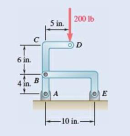
Fig. P4.66
Expert Solution & Answer

Trending nowThis is a popular solution!

Students have asked these similar questions
1. Calculation
Calculate the DOF of the following mechanis
m
2
3
1
Please enter the answer
a) Determine state of stress at all points (a, b and c). These points are located on the exteriorsurface of the beam. Point a is located along the centreline of the beam, point b is 15mmfrom the centreline and point c is located on the edge of the beam. Present yourresults in a table and ensure that your sign convention is clearly shownb) Construct Mohrs circle at this point andcalculate the principal stresses and maximum in‐plane shear stress (τmax) at pointc. sketch the resulting state of stress at this point clearly indicating themagnitude of the stresses and any angles associated with the state of stress (principal ormaximum in‐plane shear).
parts e,f,g
Chapter 4 Solutions
VECTOR MECHANICS FOR ENGINEERS: STATICS
Ch. 4.1 - Two crates, each of mass 350 kg, are placed as...Ch. 4.1 - A lever AB is hinged at C and attached to a...Ch. 4.1 - A light rod AD is supported by frictionless pegs...Ch. 4.1 - A tension of 20 N is maintained in a tape as it...Ch. 4.1 - A gardener uses a 60 N wheelbarrow to transport a...Ch. 4.1 - The gardener of Prob. 4.1 wishes to transport a...Ch. 4.1 - A 2100-lb tractor is used to lift 900 lb of grave....Ch. 4.1 - For the beam and loading shown, determine (a) the...Ch. 4.1 - A load of lumber of weight W = 25 kN is being...Ch. 4.1 - A load of lumber of weight W = 25 kN is being...
Ch. 4.1 - A hand truck is used to move a compressed-air...Ch. 4.1 - Two external shafts of a gearbox are subject to...Ch. 4.1 - Three loads are applied as shown to a light beam...Ch. 4.1 - The 10-m beam AB rests upon, but is not attached...Ch. 4.1 - The maximum allowable value of each of the...Ch. 4.1 - For the beam of Sample Prob. 4.2, determine the...Ch. 4.1 - The maximum allowable value of each of the...Ch. 4.1 - For the beam and loading shown, determine the...Ch. 4.1 - PROBLEM 4.15 The required tension in cable AB is...Ch. 4.1 - PROBLEM 4.16 Determine the maximum tension that...Ch. 4.1 - Two links AB and DE are connected by a bell crank...Ch. 4.1 - Prob. 4.18PCh. 4.1 - The bracket BCD is hinged at C and attached to a...Ch. 4.1 - The ladder AB, of length L and weight W, can be...Ch. 4.1 - The ladder AB, of length L and weight W, can be...Ch. 4.1 - A lever AB is hinged at C and attached to a...Ch. 4.1 - 4.23 and 4.24 For each of the plates and loadings...Ch. 4.1 - 4.23 and 4.24 For each of the plates and loadings...Ch. 4.1 - A rod AB, hinged at A and attached at B to cable...Ch. 4.1 - Fig. P4.25 and P4.26 4.26 A rod AB, hinged at A...Ch. 4.1 - For the frame and loading shown, determine the...Ch. 4.1 - Determine the reactions at A and C when (a) = 0,...Ch. 4.1 - Prob. 4.29PCh. 4.1 - Prob. 4.30PCh. 4.1 - Neglecting friction, determine the tension in...Ch. 4.1 - Fig. P4.31 and P4.32 4.32 Neglecting friction,...Ch. 4.1 - PROBLEM 4.33 A force P of magnitude 90 lb is...Ch. 4.1 - PROBLEM 4.34 Solve Problem 4,33 for a = 6 in,...Ch. 4.1 - Bar AC supports two 400-N loads as shown. Rollers...Ch. 4.1 - PROBLEM 4.36 A light bar AD is suspended from a...Ch. 4.1 - A 160-lb overhead garage door consists of a...Ch. 4.1 - Fig. P4.37 4.38 In Prob. 4.37, determine the...Ch. 4.1 - A movable bracket is held at rest by a cable...Ch. 4.1 - Fig. P4.39 4.40 Solve Prob. 4.39 when = 30.Ch. 4.1 - The semicircular rod ABCD is maintained in...Ch. 4.1 - Determine the range of values of for which the...Ch. 4.1 - The rig shown consists of a 1200-lb horizontal...Ch. 4.1 - Fig. P4.43 4.44 For the rig and crate of Prob....Ch. 4.1 - A 175-kg utility pole is used to support at C the...Ch. 4.1 - Knowing that the tension in wire BD is 1300 N,...Ch. 4.1 - Fig. P4.46 and P4.47 4.47 Determine the range of...Ch. 4.1 - Beam AD carries the two 40-lb loads shown. The...Ch. 4.1 - Fig. P4.48 and P4.49 4.49 For the beam and loading...Ch. 4.1 - A traffic-signal pole may be supported in the...Ch. 4.1 - A uniform rod AB with a length of l and weight of...Ch. 4.1 - Rod AD is acted upon by a vertical force P at end...Ch. 4.1 - A slender rod AB with a weigh of W is attached to...Ch. 4.1 - 4.54 and 4.55 A vertical load P is applied at end...Ch. 4.1 - 4.54 and 4.55 A vertical load P is applied at end...Ch. 4.1 - A collar B with a weight of W can move freely...Ch. 4.1 - A 400-lb weight is attached at A to the lever...Ch. 4.1 - A vertical load P is applied at end B of rod BC....Ch. 4.1 - Eight identical 500 750-mm rectangular plates,...Ch. 4.1 - A truss can be supported in the eight different...Ch. 4.2 - A 500-lb cylindrical tank, 8 ft in diameter, is to...Ch. 4.2 - Determine the reactions at A and E when =0.Ch. 4.2 - Determine (a) the value of for which the reaction...Ch. 4.2 - A 12-ft ladder, weighing 40 lb, leans against a...Ch. 4.2 - Determine the reactions at B and C when a = 30 mm.Ch. 4.2 - Determine the reactions at A and E. Fig. P4.66Ch. 4.2 - Determine the reactions at B and D when b = 60 mm....Ch. 4.2 - For the frame and loading shown, determine the...Ch. 4.2 - A 50-kg crate is attached to the trolley-beam...Ch. 4.2 - One end of rod AB rests in the corner A and the...Ch. 4.2 - For the boom and loading shown, determine (a) the...Ch. 4.2 - Prob. 4.72PCh. 4.2 - Determine the reactions at A and D when = 30.Ch. 4.2 - Determine the reactions at A and D when = 60.Ch. 4.2 - Rod AB is supported by a pin and bracket at A and...Ch. 4.2 - Solve Prob. 4.75, assuming that the 170-N force...Ch. 4.2 - The L-shaped member ACB is supported by a pin and...Ch. 4.2 - Using the method of Sec. 4.2B, solve Prob. 4.22....Ch. 4.2 - Knowing that = 30, determine the reaction (a) at...Ch. 4.2 - Prob. 4.80PCh. 4.2 - Determine the reactions at A and B when = 50....Ch. 4.2 - Determine the reactions at A and B when = 80.Ch. 4.2 - Rod AB is bent into the shape of an arc of circle...Ch. 4.2 - A slender rod of length L is attached to collars...Ch. 4.2 - Prob. 4.85PCh. 4.2 - A uniform plate girder weighing 6000 lb is held in...Ch. 4.2 - A slender rod BC with a length of L and weight W...Ch. 4.2 - A thin ring with a mass of 2 kg and radius r = 140...Ch. 4.2 - Prob. 4.89PCh. 4.2 - Prob. 4.90PCh. 4.3 - Two tape spools are attached to an axle supported...Ch. 4.3 - A 12-m pole supports a horizontal cable CD and is...Ch. 4.3 - A 20-kg cover for a roof opening is hinged at...Ch. 4.3 - END-OF-SECTION PROBLEMS 4.91 Two transmission...Ch. 4.3 - Solve Prob. 4.91, assuming that the pulley rotates...Ch. 4.3 - A small winch is used to raise a 120-lb load. Find...Ch. 4.3 - Two transmission belts pass over sheaves welded to...Ch. 4.3 - A 250 400-mm plate of mass 12 kg and a...Ch. 4.3 - Solve Prob. 4.95 for = 60. 4.95 A 250 400-mm...Ch. 4.3 - The rectangular plate shown weighs 60 lb and is...Ch. 4.3 - A load W is to be placed on the 60-lb plate of...Ch. 4.3 - An opening in a floor is covered by a 1 1.2-m...Ch. 4.3 - PROBLEM 4.100 Solve Problem 4.99, assuming that...Ch. 4.3 - PROBLEM 4.101 Two steel pipes AB and BC, each...Ch. 4.3 - PROBLEM 4.102 For the pipe assembly of Problem...Ch. 4.3 - PROBLEM 4.103 The 24-lb square plate shown is...Ch. 4.3 - PROBLEM 4.104 The table shown weighs 30 lb and has...Ch. 4.3 - PROBLEM 4.105 A 10-ft boom is acted upon by the...Ch. 4.3 - PROBLEM 4.106 The 6-m pole ABC is acted upon by a...Ch. 4.3 - PROBLEM 4.107 Solve Problem 4.106 for a = 1.5 m....Ch. 4.3 - A 3-m pole is supported by a ball-and-socket joint...Ch. 4.3 - PROBLEM 4.109 A 3-m pole is supported by a...Ch. 4.3 - PROBLEM 4.110 A 7-ft boom is held by a ball and...Ch. 4.3 - PROBLEM 4.111 A 48-in. boom is held by a...Ch. 4.3 - PROBLEM 4.112 Solve Problem 4.111, assuming that...Ch. 4.3 - PROBLEM 4.114 The bent rod ABEF is supported by...Ch. 4.3 - Prob. 4.114PCh. 4.3 - The horizontal platform ABCD weighs 60 lb and...Ch. 4.3 - PROBLEM 4.116 The lid of a roof scuttle weighs 75...Ch. 4.3 - PROBLEM 4.117 A 100-kg uniform rectangular plate...Ch. 4.3 - Solve Prob. 4.117, assuming that cable DCE is...Ch. 4.3 - PROBLEM 4.119 Solve Prob. 4.113, assuming that the...Ch. 4.3 - PROBLEM 4.120 Solve Prob. 4.115, assuming that the...Ch. 4.3 - PROBLEM 4.121 The assembly shown is used to...Ch. 4.3 - PROBLEM 4.122 The assembly shown is welded to...Ch. 4.3 - PROBLEM 4.123 The rigid L-shaped member ABC is...Ch. 4.3 - Prob. 4.124PCh. 4.3 - The rigid L-shaped member ABF is supported by a...Ch. 4.3 - Solve Prob. 4.125, assuming that the load at C has...Ch. 4.3 - Three rods are welded together to form a corner...Ch. 4.3 - Prob. 4.128PCh. 4.3 - Frame ABCD is supported by a ball-and-socket joint...Ch. 4.3 - Prob. 4.130PCh. 4.3 - Prob. 4.131PCh. 4.3 - PROBLEM 4.132 The uniform 10kg rod AB is supported...Ch. 4.3 - The frame ACD is supported by ball-and-socket...Ch. 4.3 - Solve Prob. 4.133, assuming that cable GBH is...Ch. 4.3 - The 8-ft rod AB and the 6-ft rod BC are hinged at...Ch. 4.3 - Prob. 4.136PCh. 4.3 - Prob. 4.137PCh. 4.3 - The pipe ACDE is supported by ball-and-socket...Ch. 4.3 - Solve Prob. 4.138, assuming that wire DF is...Ch. 4.3 - Two 2 4-ft plywood panels, each with a weight of...Ch. 4.3 - Solve Prob. 4.140, subject to the restriction that...Ch. 4 - A 3200-lb forklift truck is used to lift a 1700-lb...Ch. 4 - The lever BCD is hinged at C and attached to a...Ch. 4 - Determine the reactions at A and B when (a) h =0,...Ch. 4 - Neglecting friction and the radius of the pulley,...Ch. 4 - PROBLEM 4.146 Bar AD is attached at A and C to...Ch. 4 - PROBLEM 4.147 A slender rod AB, of weight W, is...Ch. 4 - PROBLEM 4.148 Determine the reactions at A and B...Ch. 4 - For the frame and loading shown, determine the...Ch. 4 - PROBLEM 4.150 A 200-mm lever and a 240-mm-diameter...Ch. 4 - The 45-lb square plate shown is supported by three...Ch. 4 - The rectangular plate shown weighs 75 lb and is...Ch. 4 - A force P is applied to a bent rod ABC, which may...
Additional Engineering Textbook Solutions
Find more solutions based on key concepts
What types of coolant are used in vehicles?
Automotive Technology: Principles, Diagnosis, And Service (6th Edition) (halderman Automotive Series)
Using your text editor, enter (that is, type in) the C++ program shown in Display 1.8. Be certain to type the f...
Problem Solving with C++ (10th Edition)
The solid steel shaft AC has a diameter of 25 mm and is supported by smooth bearings at D and E. It is coupled ...
Mechanics of Materials (10th Edition)
How is the hydrodynamic entry length defined for flow in a pipe? Is the entry length longer in laminar or turbu...
Fluid Mechanics: Fundamentals and Applications
1.2 Explain the difference between geodetic and plane
surveys,
Elementary Surveying: An Introduction To Geomatics (15th Edition)
Knowledge Booster


Learn more about
Need a deep-dive on the concept behind this application? Look no further. Learn more about this topic, mechanical-engineering and related others by exploring similar questions and additional content below.Similar questions
- Figure 9-6 9-49 An aluminum alloy plate with dimensions 20 cm x 10 cm × 2 cm needs to be cast with a secondary dendrite arm spacing of 10-2 cm (refer to Figure 9-6). What mold constant B is required (assume n = 2 )? Secondary dendrite arm spacing (cm) - 10-1 10-2 10-3 10 41 0.1 1 Copper Zinc alloys Aluminum alloys 10 100 1,000 10,000 100,000 Solidification time (s)arrow_forward9-72 Figure 9-29 shows a cylindrical riser attached to a casting. Compare the solidification times for each casting section and the riser and determine whether the riser will be effective. Figure 9-29 Т 3 6 3 8 3 6 Details A diagram shows the step-block casting. A cylinder of height "7" and diameter "3" is kept on a platform consisting of 2 steps. The width of the second step of the platform is labeled as "3". The horizontal length of the first step is labeled as "6." The horizontal length, width and height of the first step are labeled "6", "8" and "3".arrow_forward6/94 Determine the minimum coefficient of static friction for which the bar can be in static equilibrium in the config- uration shown. The bar is uniform and the fixed peg at C is small. Neglect friction at B. A L PROBLEM 6/94 B L 22arrow_forward
- Q2. For the following situation, estimate the minimum required compressive strength of 20/40 proppant. If intermediate-strength proppant is used, estimate the permeability of the proppant pack: Formation depth: 10,000 ft Overburden density: 165lbm/ft3 Poison’s ratio: 0.25 Biot constant: 0.7 Reservoir pressure: 6,500 psi Production drawdown: 2,000 and 4,000 psiarrow_forwardA 3-in.-radius drum is rigidly attached to a 5-in.-radius drum as shown. One of the drums rolls without sliding on the surface shown, and a cord is wound around the other drum. Knowing that at the instant shown. point A has a velocity of 4.875 in./sin./s and an acceleration of 15.50 in./s2in./s2 , both directed to the right, determine the accelerations of points A, B, and C of the drums. The cord is wound around the 3 inch radius drum. Point B is at the bottom of the 5 inch radius drum. Point A is at the bottom of the 3 inch radius drum. Point C is on the right edge of the 5 inch radius drum. The accelerations of point B is______ in./s2 . The accelerations of point A is ______ in./s2 ______ ⦨ °. at what angle/direction The accelerations of point C is______ in./s2 ______ ⦪ °. at what angle/direction?arrow_forwardA total volume of mud is 1,000 bbls that has a mud weight of 9.1 ppg. Calculate the volumefractions of water, Bentonite, and the weight of Bentonite used. Density of powder Bentonite is 156 lbm/ft3arrow_forward
- A 3-in.-radius drum is rigidly attached to a 5-in.-radius drum as shown. One of the drums rolls without sliding on the surface shown, and a cord is wound around the other drum. Knowing that at the instant shown. point A has a velocity of 4.875 in./sin./s and an acceleration of 15.50 in./s2in./s2 , both directed to the right, determine the accelerations of points A, B, and C of the drums. The cord is wound around the 3 inch radius drum. Point B is at the bottom of the 5 inch radius drum. Point A is at the bottom of the 3 inch radius drum. Point C is on the right edge of the 5 inch radius drum. The accelerations of point B is ______ in./s2 The accelerations of point A is ______ in./s2 _____⦨ °. The accelerations of point C is _______ in./s2 ____ ⦪ °.arrow_forwardThe average heat transfer coefficent for airflow over an odd shaped body is to be determined by mass transfer measurements and using the Chilton-Colburn analogy btwn heat and mass transfer. The experiemnt is conducted by blowing dry air at 1 atm at a free-stream velocity of 2 m/s over a body covered with a layer of naphthalene. The surface area of the body is .75 m^2, and it is observed that 100 g of maphthalene has sublimated in 45 min. During the experiemnt, both the body and the air were kep at 25oC, at which the vapor pressure and mass diffusivity of naphthalene are 11 Pa and Dab=0.61*10^-5 m^2/s respectively. Determine the heat transfer coefficent under the same flow conditions over the same geometry.arrow_forwardAuto Controls Design a PID controller for thefollowing system so that the modified system satisfies the followingspecifications : 1. settling time ,ts = 1.96 s and % Overshoot Mp = 70.7 % Assume a non-dominant pole at s = -15 to solve the problem The plot the compensated andThen plot the uncompensated system in MATLAB. what can you see from the plot ? what is your observation ?arrow_forward
- Auto Controls The figure is a schematic diagram of an aircraft elevator control system. The input to the systemin the deflection angle of the control lever , and the output is the elevator angle phi.show that for each angle theta of the control lever ,there is a corresponding elevator angle phi. Then find Y(s)/theta(s) and simplify the resulting transfer function . Also note from the diagram that y and phi is relatedarrow_forwardFresh water is planned to be pumped in a certain pipe at constant pumping rate of 6.5 gpm. If water density and viscosity are 8.34 ppg and 1.0 cp, what is the minimum pipe inside diameter that make the fluid flow behave as turbulent flow?arrow_forwardUSE MATLAB ONLY provide typed code Turbomachienery . GIven: vx = 185 m/s, flow angle = 60 degrees, R = 0.5, U = 150 m/s, b2 = -a3, a2 = -b3 Find: velocity triangle , a. magnitude of abs vel leaving rotor (m/s) b. flow absolute angles (a1, a2, a3) 3. flow rel angles (b2, b3) d. specific work done e. use code to draw vel. diagram Use this code for plot % plots Velocity Tri. in Ch4 function plotveltri(al1,al2,al3,b2,b3) S1L = [0 1]; V1x = [0 0]; V1s = [0 1*tand(al3)]; S2L = [2 3]; V2x = [0 0]; V2s = [0 1*tand(al2)]; W2s = [0 1*tand(b2)]; U2x = [3 3]; U2y = [1*tand(b2) 1*tand(al2)]; S3L = [4 5]; V3x = [0 0]; V3r = [0 1*tand(al3)]; W3r = [0 1*tand(b3)]; U3x = [5 5]; U3y = [1*tand(b3) 1*tand(al3)]; plot(S1L,V1x,'k',S1L,V1s,'r',... S2L,V2x,'k',S2L,V2s,'r',S2L,W2s,'b',U2x,U2y,'g',... S3L,V3x,'k',S3L,V3r,'r',S3L,W3r,'b',U3x,U3y,'g',...... 'LineWidth',2,'MarkerSize',10),... axis([-1 6 -4 4]), ... title('Velocity Triangle'), ... xlabel('x'),ylarrow_forward
arrow_back_ios
SEE MORE QUESTIONS
arrow_forward_ios
Recommended textbooks for you
 Elements Of ElectromagneticsMechanical EngineeringISBN:9780190698614Author:Sadiku, Matthew N. O.Publisher:Oxford University Press
 Mechanics of Materials (10th Edition)Mechanical EngineeringISBN:9780134319650Author:Russell C. HibbelerPublisher:PEARSON
 Thermodynamics: An Engineering ApproachMechanical EngineeringISBN:9781259822674Author:Yunus A. Cengel Dr., Michael A. BolesPublisher:McGraw-Hill Education
 Control Systems EngineeringMechanical EngineeringISBN:9781118170519Author:Norman S. NisePublisher:WILEY
 Mechanics of Materials (MindTap Course List)Mechanical EngineeringISBN:9781337093347Author:Barry J. Goodno, James M. GerePublisher:Cengage Learning
 Engineering Mechanics: StaticsMechanical EngineeringISBN:9781118807330Author:James L. Meriam, L. G. Kraige, J. N. BoltonPublisher:WILEY
Elements Of Electromagnetics
Mechanical Engineering
ISBN:9780190698614
Author:Sadiku, Matthew N. O.
Publisher:Oxford University Press
Mechanics of Materials (10th Edition)
Mechanical Engineering
ISBN:9780134319650
Author:Russell C. Hibbeler
Publisher:PEARSON
Thermodynamics: An Engineering Approach
Mechanical Engineering
ISBN:9781259822674
Author:Yunus A. Cengel Dr., Michael A. Boles
Publisher:McGraw-Hill Education
Control Systems Engineering
Mechanical Engineering
ISBN:9781118170519
Author:Norman S. Nise
Publisher:WILEY
Mechanics of Materials (MindTap Course List)
Mechanical Engineering
ISBN:9781337093347
Author:Barry J. Goodno, James M. Gere
Publisher:Cengage Learning
Engineering Mechanics: Statics
Mechanical Engineering
ISBN:9781118807330
Author:James L. Meriam, L. G. Kraige, J. N. Bolton
Publisher:WILEY
Extent of Reaction; Author: LearnChemE;https://www.youtube.com/watch?v=__stMf3OLP4;License: Standard Youtube License