
Concept explainers
A truss can be supported in the eight different ways shown A connections consist of smooth pins, rollers, or short links. For case, answer the questions listed in Prob. 4.59, and, wherever possible, compute the reactions, assuming that the magnitude force P is 12 kips.
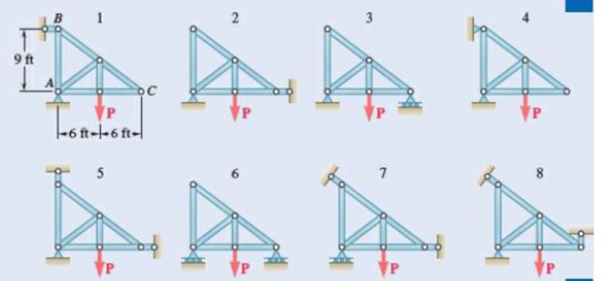
Fig. P4.60
(a)
Find whether the plate is completely, partially, or improperly constrained.
Answer to Problem 4.60P
The plate in figure 1 is
The plate figure 2 is
The plate figure 3 is
The plate figure 4 is
The plate figure 5 is
The plate figure 6 is
The plate figure 7 is
The plate figure 8 is
Explanation of Solution
Given information:
The magnitude of the force P is 12 kips.
Calculation:
Figure 1:
Show the free-body diagram of the Figure 1.
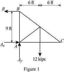
The three reactions in the plate behave like non-concurrent and non-parallel force system.
The plate in figure 1 is
Figure 2:
Show the free-body diagram of the Figure 2.
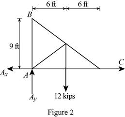
The three reactions in the plate behave like concurrent force system.
The plate figure 2 is
Figure 3:
Show the free-body diagram of the Figure 3.
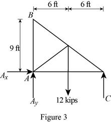
The three reactions in the plate behave like non-concurrent and non-parallel force system.
The plate figure 3 is
Figure 4:
Show the free-body diagram of the Figure 4.
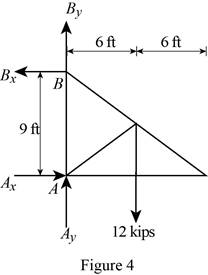
The four reactions in the plate behave like non-concurrent and non-parallel force system.
The plate figure 4 is
Figure 5:
Show the free-body diagram of the Figure 5.
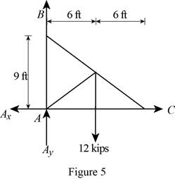
The four reactions in the plate behave like concurrent force system.
The plate figure 5 is
Figure 6:
Show the free-body diagram of the Figure 6.
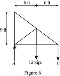
The two reactions in the plate behave like concurrent force system.
The plate figure 6 is
Figure 7:
Show the free-body diagram of the Figure 7.
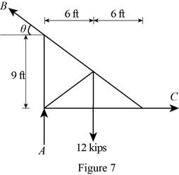
The three reactions in the plate behave like non-concurrent and non-parallel force system.
The plate figure 7 is
Figure 8:
Show the free-body diagram of the Figure 8.
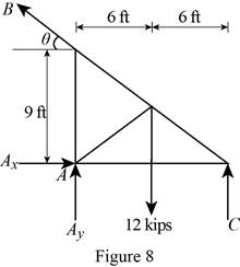
The four reactions in the plate behave like non-concurrent and non-parallel force system.
The plate figure 8 is
(b)
Find whether the reactions are statically determinate or indeterminate.
Answer to Problem 4.60P
The reactions in figure 1 is
The reactions in figure 2 is
The reactions in figure 3 is
The reactions in figure 4 is
The reactions in figure 5 is
The reactions in figure 6 is
The reactions in figure 7 is
The reactions in figure 8 is
Explanation of Solution
Refer Figure 1:
The equilibrium equations are;
The equilibrium equations are enough to determine the unknown reactions.
The reactions in figure 1 is
Refer Figure 2:
The equilibrium equations are;
The equilibrium equations are enough to determine the unknown reactions.
But the plate is improperly constrained and the plate is not in equilibrium.
The reactions in figure 2 is
Refer Figure 3:
The equilibrium equations are;
The equilibrium equations are enough to determine the unknown reactions.
The reactions in figure 3 is
Refer Figure 4:
The equilibrium equations are;
The equilibrium equations are not enough to determine the unknown reactions.
The reactions in figure 4 is
Refer Figure 5:
The equilibrium equations are;
The equilibrium equations are enough to determine the unknown reactions.
But the plate is improperly constrained and the plate is not in equilibrium.
The reactions in figure 5 is
Refer Figure 6:
The equilibrium equations are;
The equilibrium equations are enough to determine the unknown reactions.
The reactions in figure 6 is
Refer Figure 7:
The equilibrium equations are;
The equilibrium equations are enough to determine the unknown reactions.
The reactions in figure 7 is
Refer Figure 8:
The equilibrium equations are;
The equilibrium equations are not enough to determine the unknown reactions.
The reactions in figure 8 is
(c)
Find whether the equilibrium of the plate is maintained.
Answer to Problem 4.60P
The reactions in the plate 1 are
The plate 1 is in
The plate 2 is in
The reactions in the plate 3 are
The plate 3 is in
The reactions in the plate 4 are
The plate 4 is in
The plate 5 is in
The reactions in the plate 6 are
The plate 6 is in
The reactions in the plate 7 are
The plate 7 is in
The reactions in the plate 8 are
The plate 8 is in
Explanation of Solution
Refer Figure 1:
The equilibrium equations are;
Take moment about point A.
Resolve the horizontal component of forces.
Resolve the vertical component of forces.
Find the resultant force at A;
Find the angle
Therefore, the reactions in the plate 1 are
The plate 1 is in
Refer Figure 2:
The equilibrium equations are;
The moment about point A is not equal to zero.
The plate 2 is in
Refer Figure 3:
The equilibrium equations are;
Take moment about point A.
Resolve the horizontal component of forces.
Resolve the vertical component of forces.
Therefore, the reactions in the plate 3 are
The plate 3 is in
Refer Figure 4:
The equilibrium equations are;
Take moment about point A.
Resolve the horizontal component of forces.
Resolve the vertical component of forces.
Therefore, the reactions in the plate 4 are
The plate 4 is in
Refer Figure 5:
The equilibrium equations are;
The moment about point A is not equal to zero.
The plate 5 is in
Refer Figure 6:
The equilibrium equations are;
Take moment about point A.
Resolve the vertical component of forces.
Therefore, the reactions in the plate 6 are
The plate 6 is in
Refer Figure 7:
The equilibrium equations are;
Find the angle
Take moment about point A.
Resolve the horizontal component of forces.
Resolve the vertical component of forces.
Therefore, the reactions in the plate 7 are
The plate 7 is in
Refer Figure 8:
The equilibrium equations are;
Take moment about point C.
Therefore, the reactions in the plate 8 are
The plate 8 is in
Want to see more full solutions like this?
Chapter 4 Solutions
VEC MECH 180-DAT EBOOK ACCESS(STAT+DYNA)
- what is an air preheater, what are formulas, and their importance, define the diagram, and give me a script on how to explain the design of an air preheater, and how did values end up in that number. based on standardsarrow_forwardQf, Qa,Qm, Qcon,Qfg, Qbd, Qref,Qloss ( meaning, formula, percentage, and importance of higher value na qf, qa etc)arrow_forwardThe beam is supported by a fixed support at point C and a roller at point A. It also has an internal hinge at point B. The beam supports a point load at point D, a moment at point A and a distributed load on segment BC. a. calculate the support reactions at points A and C b. calculate the internal resultant loadings (N, V, M) at points E and F, which lies in the middle between points A and D P = 4 kip Ma = 5 kip-ft w1 = 3 kip/ft and w2 = 4 kip/ft a = 3 ftarrow_forward
- From the image of the pyramid, I want to find what s1 hat, s2 hat, and s3 hat are. I think s3 hat is just equal to e3 hat right? What about the others?arrow_forward(a) What kind of equation is it?(b) Is it linear or non-linear?(c) Is it a coupled system or uncoupled?arrow_forwardWhat kind of system is presented in Figure 2? Open loop or closed loop?arrow_forward
- What are the control hardware shown in the Figure?arrow_forwardQuestion 1. A tube rotates in the horizontal ry plane with a constant angular velocity w about the z-axis. A particle of mass m is released from a radial distance R when the tube is in the position shown. This problem is based on problem 3.2 in the text. R m 2R Figure 1 x a) Draw a free body diagram of the particle if the tube is frictionless. b) Draw a free body diagram of the particle if the coefficient of friction between the sides of the tube and the particle is = k = p. c) For the case where the tube is frictionless, what is the radial speed at which the particle leaves the tube? d) For the case where there is friction, derive a differential equation that would allow you to solve for the radius of the particle as a function of time. I'm only looking for the differential equation. DO NOT solve it. 1 e) If there is no friction, what is the angle of the tube when the particle exits? • Hint: You may need to solve a differential equation for the last part. The "potentially useful…arrow_forwardQuestion 2. A smooth uniform sphere of mass m and radius r is squeezed between two massless levers, each of length 1, which are inclined at an angle with the vertical. A mechanism at pivot point O ensures that the angles & remain the same at all times so that the sphere moves straight upward. This problem is based on Problem 3-1 in the text. P P r Figure 2 a) Draw appropriate freebody diagrams of the system assuming that there is no friction. b) Draw appropriate freebody diagrams of the system assuming that there is a coefficient of friction between the sphere and the right lever of μ. c) If a force P is applied between the ends of the levers (shown in the diagram), and there is no friction, what is the acceleration of the sphere when = 30°arrow_forward
- If you had a matrix A = [1 2 3; 4 5 6; 7 8 9] and a matrix B = [1 2 3], how would you cross multiply them i.e. what is the cross product of AxB. what would be the cross product of a dyadic with a vector?arrow_forwardProblem 3: The inertia matrix can be written in dyadic form which is particularly useful when inertia information is required in various vector bases. On the next page is a right rectangular pyramid of total mass m. Note the location of point Q. (a) Determine the inertia dyadic for the pyramid P, relative to point Q, i.e., 7%, for unit vectors ₁₁, 2, 3.arrow_forwardCan you solve for v? Also, what is A x uarrow_forward
 Elements Of ElectromagneticsMechanical EngineeringISBN:9780190698614Author:Sadiku, Matthew N. O.Publisher:Oxford University Press
 Mechanics of Materials (10th Edition)Mechanical EngineeringISBN:9780134319650Author:Russell C. HibbelerPublisher:PEARSON
 Thermodynamics: An Engineering ApproachMechanical EngineeringISBN:9781259822674Author:Yunus A. Cengel Dr., Michael A. BolesPublisher:McGraw-Hill Education
 Control Systems EngineeringMechanical EngineeringISBN:9781118170519Author:Norman S. NisePublisher:WILEY
 Mechanics of Materials (MindTap Course List)Mechanical EngineeringISBN:9781337093347Author:Barry J. Goodno, James M. GerePublisher:Cengage Learning
 Engineering Mechanics: StaticsMechanical EngineeringISBN:9781118807330Author:James L. Meriam, L. G. Kraige, J. N. BoltonPublisher:WILEY


