VECTOR MECHANICS FOR ENGINEERS: STATICS
12th Edition
ISBN: 9781259977121
Author: BEER
Publisher: MCG
bartleby

Videos

Textbook Question
Book Icon
Chapter 4.1, Problem 4.27P

For the frame and loading shown, determine the reactions at A E when (a) α = 30º, (b) α = 45 º.
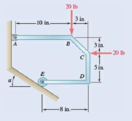
Chapter 4.1, Problem 4.27P, For the frame and loading shown, determine the reactions at A E when (a)  = 30, (b)  = 45 . Fig.

Fig. P4.27

(a)

Expert Solution
Check Mark
To determine

The reaction at A and E when α=30°.

Answer to Problem 4.27P

The reaction at A is 8.29lb and it acts angle 58.0° below positive x axis and reaction at E is 31.2lb and it acts at angle of 60.0° above positive x axis.

Explanation of Solution

Forces acting upward and rightward are considered as positive and the torque acting counter clockwise is considered as positive.

Let A is the reaction at the point A shown in figure P4.25, Ax and Ay are the x component and y component of reaction at A. Let E is the reaction at point E.

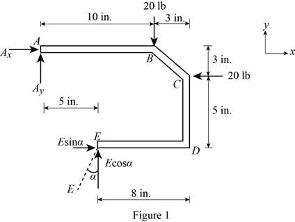
The free body diagram is sketched below as figure 1.
VECTOR MECHANICS FOR ENGINEERS: STATICS, Chapter 4.1, Problem 4.27P

Here, A is the magnitude of reaction at point A , E is the magnitude of reaction at point E , α is the angle that reaction E makes with y axis, Ax is the magnitude of the x component of reaction at A and Ay is the magnitude of y component of reaction at A.

Write the expression for the moment at A

MA=F×D (I)

Here, MA is the net moment at A, F is the force, and D is the perpendicular distance between the A and the point where force is experienced.

Above equation implies that net moment at any point is the sum of product of each force acting on the system and perpendicular distance of the force about that point.

The moment at A is due to the x and y component of reaction E , 20lb force at B and 20lb force at C.

The angle α is equal to 30°.

The complete expression of moment MA at point A.

MA=Ex(8in.)+Ey(5in.)(20lb)(10in.)(20lb)(3in.) (II)

Here, MA is the sum of all moment of force at A , Ex and Ey are the x and y component of E.

From figure 1, write the expression for the x component of reaction E.

Ex=Esinα

From figure 1, write the expression for the y component of reaction E.

Ey=Ecosα

At equilibrium, the sum of the moment acting at A will be zero.

Write the expression for the total moment acting at A.

MA=Esinα(8in.)+Ecosα(5in.)(20lb)(10in.)(20lb)(3in.)=0 (III)

The forces along the x direction are the x component of reaction A, 20lb force acting at C an d the x component of reaction E.

Therefore, write the expression for the net force along the x direction.

Fx=Ax20lb+Esinα (IV)

Here, Fx is the sum of all force along the x direction.

At equilibrium, the net force along the x direction will be zero.

Fx=Ax20lb+Esinα=0 (V)

The forces along the x direction are the y component of reaction A, 20lb force acting at B and the y component of reaction E.

Therefore, write the expression for the net force along the y direction.

Fy=Ay20lb+Ecosα (VI)

Here, Fy is the sum of all force along the y direction.

At equilibrium, the net force along the y direction will be zero.

Fy=Ay20lb+Ecosα=0 (VII)

Write the expression for the magnitude of net reaction at A.

A=Ax2+Ay2 (VIII)

Here, A is the magnitude of net reaction at A.

Let θ be the angle between A and x axis.

Therefore, write the expression for the tanθ.

tanθ=AyAx (IX)

Calculation:

Substitute 30° for α and rearrange the equation (III) to get E.

Esin(30°)(8in.)+Ecos(30°)(5in.)(20lb)(10in.)(20lb)(3in.)=0

E=(20lb)(10in.)+(20lb)(3in.)sin(30°)(8in.)+cos(30°)(5in.)=31.212lb=31.2lb

Substitute 30° for α and 31.212lb for E in equation (V) to get Ax.

Ax20lb+(31.212lb)sin(30°)=0

Ax=20lb(31.212lb)sin(30°)=4.394lb

Substitute 30° for α and 31.212lb for E in equation (VII) to get Ay.

Ay20lb+(31.212lb)cos(30°)=0

Ay=20lb(31.212lb)cos(30°)=7.03lb

The negative sign indicates that direction of Ay is along y axis.

Substitute 4.394lb for Ax and 7.03lb for Ay in equation (VIII) to get A.

A=(4.394lb)2+(7.03lb)2=8.29lb

Substitute 4.394lb for Ax and 7.03lb for Ay in equation (IX) to get θ.

tanθ=7.03lb4.394lbθ=58.0°

The negative sign indicates that A makes 58.0° below positive x axis.

Therefore, the reaction at A is 8.29lb and it acts angle 58.0° below positive x axis and reaction at E is 31.2lb and it acts at angle of 60.0° above positive x axis.

(b)

Expert Solution
Check Mark
To determine

The reaction at A and E when α=45°.

Answer to Problem 4.27P

The reaction at A is 0lb and reaction at E is 28.3lb and it acts at angle of 45.0° above positive x axis.

Explanation of Solution

Take all vectors along the x axis and y axis as positive.

Let A is the reaction at the point A shown in figure P4.27, Ax and Ay are the x component and y component of reaction at A. Let E is the reaction at point E.

The free body diagram is sketched in figure 1.

Write the expression for the moment at A

MA=F×D (I)

Here, MA is the net moment at A, F is the force, and D is the perpendicular distance between the A and the point where force is experienced.

Above equation implies that net moment at any point is the sum of product of each force acting on the system and perpendicular distance of the force and the point.

The moment at A is due to the x and y component of reaction E , 20lb force at B and 20lb force at C.

The angle α is equal to 45°.

Thus, the complete expression of net anticlockwise moment MA at point A.

MA=Ex(8in.)+Ey(5in.)(20lb)(10in.)(20lb)(3in.) (II)

Here, MA is the sum of all moment of force at A , Ex and Ey are the x and y component of E.

From figure 1, write the expression for the x component of reaction E.

Ex=Esinα

From figure 1, write the expression for the y component of reaction E.

Ey=Ecosα

At equilibrium, the sum of the moment acting at A will be zero.

Write the expression for the total moment acting at A.

MA=Esinα(8in.)+Ecosα(5in.)(20lb)(10in.)(20lb)(3in.)=0 (III)

The forces along the x direction are the x component of reaction A, 20lb force acting at C an d the x component of reaction E.

Therefore, write the expression for the net force along the x direction.

Fx=Ax20lb+Esinα (IV)

Here, Fx is the sum of all force along the x direction.

At equilibrium, the net force along the x direction will be zero.

Fx=Ax20lb+Esinα=0 (V)

The forces along the x direction are the y component of reaction A, 20lb force acting at B and the y component of reaction E.

Therefore, write the expression for the net force along the y direction.

Fy=Ay20lb+Ecosα (VI)

Here, Fy is the sum of all force along the y direction.

At equilibrium, the net force along the y direction will be zero.

Fy=Ay20lb+Ecosα=0 (VII)

Write the expression for the magnitude of net reaction at A.

A=Ax2+Ay2 (VIII)

Here, A is the magnitude of net reaction at A.

Let θ be the angle between A and x axis.

Therefore, write the expression for the tanθ.

tanθ=AyAx (IX)

Calculation:

Substitute 45° for α and rearrange the equation (III) to get E.

Esin(45°)(8in.)+Ecos(45°)(5in.)(20lb)(10in.)(20lb)(3in.)=0

E=(20lb)(10in.)+(20lb)(3in.)sin(45°)(8in.)+cos(45°)(5in.)=28.28lb=28.3lb

Substitute 45° for α and 28.28lb for E in equation (V) to get Ax.

Ax20lb+(28.28lb)sin(45°)=0

Ax=20lb(28.28lb)sin(45°)=0lb

Substitute 45° for α and 28.28lb for E in equation (VII) to get Ay.

Ay20lb+(28.28lb)cos(45°)=0

Ay=20lb(28.28lb)cos(45°)=0lb

The negative sign indicates that direction of Ay is along y axis.

Substitute 0lb for Ax and 0lb for Ay in equation (VIII) to get A.

A=(0lb)2+(0lb)2=0lb

Therefore, the reaction at A is 0lb and reaction at E is 28.3lb and it acts at angle of 45.0° above positive x axis.

Want to see more full solutions like this?

Subscribe now to access step-by-step solutions to millions of textbook problems written by subject matter experts!
Students have asked these similar questions
Q.3) The rod is supported by a roller at A and a smooth collar at B. The collar is fixed to the rod AB but is allowed to slip along rod CD. Determine the support reactions at A and at B, the moment reaction in the collar at B. 900 N 45° 2 m B 600 N m D 45°
Neglecting friction, determine the tension in cable ABD and the reaction at C w hen 0=45°.Fig. P4.34
Problem 4.122

Chapter 4 Solutions

VECTOR MECHANICS FOR ENGINEERS: STATICS

Ch. 4.1 - A hand truck is used to move a compressed-air...Ch. 4.1 - Two external shafts of a gearbox are subject to...Ch. 4.1 - Three loads are applied as shown to a light beam...Ch. 4.1 - The 10-m beam AB rests upon, but is not attached...Ch. 4.1 - The maximum allowable value of each of the...Ch. 4.1 - For the beam of Sample Prob. 4.2, determine the...Ch. 4.1 - The maximum allowable value of each of the...Ch. 4.1 - For the beam and loading shown, determine the...Ch. 4.1 - PROBLEM 4.15 The required tension in cable AB is...Ch. 4.1 - PROBLEM 4.16 Determine the maximum tension that...Ch. 4.1 - Two links AB and DE are connected by a bell crank...Ch. 4.1 - Prob. 4.18PCh. 4.1 - The bracket BCD is hinged at C and attached to a...Ch. 4.1 - The ladder AB, of length L and weight W, can be...Ch. 4.1 - The ladder AB, of length L and weight W, can be...Ch. 4.1 - A lever AB is hinged at C and attached to a...Ch. 4.1 - 4.23 and 4.24 For each of the plates and loadings...Ch. 4.1 - 4.23 and 4.24 For each of the plates and loadings...Ch. 4.1 - A rod AB, hinged at A and attached at B to cable...Ch. 4.1 - Fig. P4.25 and P4.26 4.26 A rod AB, hinged at A...Ch. 4.1 - For the frame and loading shown, determine the...Ch. 4.1 - Determine the reactions at A and C when (a) = 0,...Ch. 4.1 - Prob. 4.29PCh. 4.1 - Prob. 4.30PCh. 4.1 - Neglecting friction, determine the tension in...Ch. 4.1 - Fig. P4.31 and P4.32 4.32 Neglecting friction,...Ch. 4.1 - PROBLEM 4.33 A force P of magnitude 90 lb is...Ch. 4.1 - PROBLEM 4.34 Solve Problem 4,33 for a = 6 in,...Ch. 4.1 - Bar AC supports two 400-N loads as shown. Rollers...Ch. 4.1 - PROBLEM 4.36 A light bar AD is suspended from a...Ch. 4.1 - A 160-lb overhead garage door consists of a...Ch. 4.1 - Fig. P4.37 4.38 In Prob. 4.37, determine the...Ch. 4.1 - A movable bracket is held at rest by a cable...Ch. 4.1 - Fig. P4.39 4.40 Solve Prob. 4.39 when = 30.Ch. 4.1 - The semicircular rod ABCD is maintained in...Ch. 4.1 - Determine the range of values of for which the...Ch. 4.1 - The rig shown consists of a 1200-lb horizontal...Ch. 4.1 - Fig. P4.43 4.44 For the rig and crate of Prob....Ch. 4.1 - A 175-kg utility pole is used to support at C the...Ch. 4.1 - Knowing that the tension in wire BD is 1300 N,...Ch. 4.1 - Fig. P4.46 and P4.47 4.47 Determine the range of...Ch. 4.1 - Beam AD carries the two 40-lb loads shown. The...Ch. 4.1 - Fig. P4.48 and P4.49 4.49 For the beam and loading...Ch. 4.1 - A traffic-signal pole may be supported in the...Ch. 4.1 - A uniform rod AB with a length of l and weight of...Ch. 4.1 - Rod AD is acted upon by a vertical force P at end...Ch. 4.1 - A slender rod AB with a weigh of W is attached to...Ch. 4.1 - 4.54 and 4.55 A vertical load P is applied at end...Ch. 4.1 - 4.54 and 4.55 A vertical load P is applied at end...Ch. 4.1 - A collar B with a weight of W can move freely...Ch. 4.1 - A 400-lb weight is attached at A to the lever...Ch. 4.1 - A vertical load P is applied at end B of rod BC....Ch. 4.1 - Eight identical 500 750-mm rectangular plates,...Ch. 4.1 - A truss can be supported in the eight different...Ch. 4.2 - A 500-lb cylindrical tank, 8 ft in diameter, is to...Ch. 4.2 - Determine the reactions at A and E when =0.Ch. 4.2 - Determine (a) the value of for which the reaction...Ch. 4.2 - A 12-ft ladder, weighing 40 lb, leans against a...Ch. 4.2 - Determine the reactions at B and C when a = 30 mm.Ch. 4.2 - Determine the reactions at A and E. Fig. P4.66Ch. 4.2 - Determine the reactions at B and D when b = 60 mm....Ch. 4.2 - For the frame and loading shown, determine the...Ch. 4.2 - A 50-kg crate is attached to the trolley-beam...Ch. 4.2 - One end of rod AB rests in the corner A and the...Ch. 4.2 - For the boom and loading shown, determine (a) the...Ch. 4.2 - Prob. 4.72PCh. 4.2 - Determine the reactions at A and D when = 30.Ch. 4.2 - Determine the reactions at A and D when = 60.Ch. 4.2 - Rod AB is supported by a pin and bracket at A and...Ch. 4.2 - Solve Prob. 4.75, assuming that the 170-N force...Ch. 4.2 - The L-shaped member ACB is supported by a pin and...Ch. 4.2 - Using the method of Sec. 4.2B, solve Prob. 4.22....Ch. 4.2 - Knowing that = 30, determine the reaction (a) at...Ch. 4.2 - Prob. 4.80PCh. 4.2 - Determine the reactions at A and B when = 50....Ch. 4.2 - Determine the reactions at A and B when = 80.Ch. 4.2 - Rod AB is bent into the shape of an arc of circle...Ch. 4.2 - A slender rod of length L is attached to collars...Ch. 4.2 - Prob. 4.85PCh. 4.2 - A uniform plate girder weighing 6000 lb is held in...Ch. 4.2 - A slender rod BC with a length of L and weight W...Ch. 4.2 - A thin ring with a mass of 2 kg and radius r = 140...Ch. 4.2 - Prob. 4.89PCh. 4.2 - Prob. 4.90PCh. 4.3 - Two tape spools are attached to an axle supported...Ch. 4.3 - A 12-m pole supports a horizontal cable CD and is...Ch. 4.3 - A 20-kg cover for a roof opening is hinged at...Ch. 4.3 - END-OF-SECTION PROBLEMS 4.91 Two transmission...Ch. 4.3 - Solve Prob. 4.91, assuming that the pulley rotates...Ch. 4.3 - A small winch is used to raise a 120-lb load. Find...Ch. 4.3 - Two transmission belts pass over sheaves welded to...Ch. 4.3 - A 250 400-mm plate of mass 12 kg and a...Ch. 4.3 - Solve Prob. 4.95 for = 60. 4.95 A 250 400-mm...Ch. 4.3 - The rectangular plate shown weighs 60 lb and is...Ch. 4.3 - A load W is to be placed on the 60-lb plate of...Ch. 4.3 - An opening in a floor is covered by a 1 1.2-m...Ch. 4.3 - PROBLEM 4.100 Solve Problem 4.99, assuming that...Ch. 4.3 - PROBLEM 4.101 Two steel pipes AB and BC, each...Ch. 4.3 - PROBLEM 4.102 For the pipe assembly of Problem...Ch. 4.3 - PROBLEM 4.103 The 24-lb square plate shown is...Ch. 4.3 - PROBLEM 4.104 The table shown weighs 30 lb and has...Ch. 4.3 - PROBLEM 4.105 A 10-ft boom is acted upon by the...Ch. 4.3 - PROBLEM 4.106 The 6-m pole ABC is acted upon by a...Ch. 4.3 - PROBLEM 4.107 Solve Problem 4.106 for a = 1.5 m....Ch. 4.3 - A 3-m pole is supported by a ball-and-socket joint...Ch. 4.3 - PROBLEM 4.109 A 3-m pole is supported by a...Ch. 4.3 - PROBLEM 4.110 A 7-ft boom is held by a ball and...Ch. 4.3 - PROBLEM 4.111 A 48-in. boom is held by a...Ch. 4.3 - PROBLEM 4.112 Solve Problem 4.111, assuming that...Ch. 4.3 - PROBLEM 4.114 The bent rod ABEF is supported by...Ch. 4.3 - Prob. 4.114PCh. 4.3 - The horizontal platform ABCD weighs 60 lb and...Ch. 4.3 - PROBLEM 4.116 The lid of a roof scuttle weighs 75...Ch. 4.3 - PROBLEM 4.117 A 100-kg uniform rectangular plate...Ch. 4.3 - Solve Prob. 4.117, assuming that cable DCE is...Ch. 4.3 - PROBLEM 4.119 Solve Prob. 4.113, assuming that the...Ch. 4.3 - PROBLEM 4.120 Solve Prob. 4.115, assuming that the...Ch. 4.3 - PROBLEM 4.121 The assembly shown is used to...Ch. 4.3 - PROBLEM 4.122 The assembly shown is welded to...Ch. 4.3 - PROBLEM 4.123 The rigid L-shaped member ABC is...Ch. 4.3 - Prob. 4.124PCh. 4.3 - The rigid L-shaped member ABF is supported by a...Ch. 4.3 - Solve Prob. 4.125, assuming that the load at C has...Ch. 4.3 - Three rods are welded together to form a corner...Ch. 4.3 - Prob. 4.128PCh. 4.3 - Frame ABCD is supported by a ball-and-socket joint...Ch. 4.3 - Prob. 4.130PCh. 4.3 - Prob. 4.131PCh. 4.3 - PROBLEM 4.132 The uniform 10kg rod AB is supported...Ch. 4.3 - The frame ACD is supported by ball-and-socket...Ch. 4.3 - Solve Prob. 4.133, assuming that cable GBH is...Ch. 4.3 - The 8-ft rod AB and the 6-ft rod BC are hinged at...Ch. 4.3 - Prob. 4.136PCh. 4.3 - Prob. 4.137PCh. 4.3 - The pipe ACDE is supported by ball-and-socket...Ch. 4.3 - Solve Prob. 4.138, assuming that wire DF is...Ch. 4.3 - Two 2 4-ft plywood panels, each with a weight of...Ch. 4.3 - Solve Prob. 4.140, subject to the restriction that...Ch. 4 - A 3200-lb forklift truck is used to lift a 1700-lb...Ch. 4 - The lever BCD is hinged at C and attached to a...Ch. 4 - Determine the reactions at A and B when (a) h =0,...Ch. 4 - Neglecting friction and the radius of the pulley,...Ch. 4 - PROBLEM 4.146 Bar AD is attached at A and C to...Ch. 4 - PROBLEM 4.147 A slender rod AB, of weight W, is...Ch. 4 - PROBLEM 4.148 Determine the reactions at A and B...Ch. 4 - For the frame and loading shown, determine the...Ch. 4 - PROBLEM 4.150 A 200-mm lever and a 240-mm-diameter...Ch. 4 - The 45-lb square plate shown is supported by three...Ch. 4 - The rectangular plate shown weighs 75 lb and is...Ch. 4 - A force P is applied to a bent rod ABC, which may...
Knowledge Booster
Background pattern image
Mechanical Engineering
Learn more about
Need a deep-dive on the concept behind this application? Look no further. Learn more about this topic, mechanical-engineering and related others by exploring similar questions and additional content below.
Similar questions
SEE MORE QUESTIONS
Recommended textbooks for you
Text book image
Elements Of Electromagnetics
Mechanical Engineering
ISBN:9780190698614
Author:Sadiku, Matthew N. O.
Publisher:Oxford University Press
Text book image
Mechanics of Materials (10th Edition)
Mechanical Engineering
ISBN:9780134319650
Author:Russell C. Hibbeler
Publisher:PEARSON
Text book image
Thermodynamics: An Engineering Approach
Mechanical Engineering
ISBN:9781259822674
Author:Yunus A. Cengel Dr., Michael A. Boles
Publisher:McGraw-Hill Education
Text book image
Control Systems Engineering
Mechanical Engineering
ISBN:9781118170519
Author:Norman S. Nise
Publisher:WILEY
Text book image
Mechanics of Materials (MindTap Course List)
Mechanical Engineering
ISBN:9781337093347
Author:Barry J. Goodno, James M. Gere
Publisher:Cengage Learning
Text book image
Engineering Mechanics: Statics
Mechanical Engineering
ISBN:9781118807330
Author:James L. Meriam, L. G. Kraige, J. N. Bolton
Publisher:WILEY
Extent of Reaction; Author: LearnChemE;https://www.youtube.com/watch?v=__stMf3OLP4;License: Standard Youtube License