
PROGRAMMABLE LOGIC CONTROLLERS (LOOSE PA
5th Edition
ISBN: 9781264206216
Author: Petruzella
Publisher: MCG
expand_more
expand_more
format_list_bulleted
Concept explainers
Question
Chapter 4, Problem 5RQ
Program Plan Intro
Logic gate:
- Logic gate is an electronic circuit that is used to take logical decisions based on the input.
- It contains one or more number of inputs and one output.
- The working of logic gate is based on the binary principle that has two states either logic 0 or logic 1.
- The output of logic gate is produced when it satisfies any of its logic conditions.
- The logic condition depends upon the type of the gates and the number of inputs.
- The primary logic gates include AND, OR and NOT and the combinations of these gates are used to implement any of the other logic gates.
AND gate:
- The AND gate refers to a logic gate whose output will be HIGH only when all the inputs are HIGH.
- The output of AND gate will be LOW when any one of its input is LOW.
- The symbol to represent AND gate is given below:
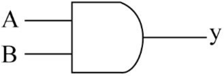
- The truth table for AND gate is as follows:
| INPUT A | INPUT B | OUTPUT Y |
| 0 | 0 | 0 |
| 0 | 1 | 0 |
| 1 | 0 | 0 |
| 1 | 1 | 1 |
OR gate:
- The OR gate refers to a logic gate whose output will be HIGH when any one of its inputs are HIGH.
- The output of AND gate will be LOW when both the inputs are LOW.
- The symbol to represent OR gate is given below:
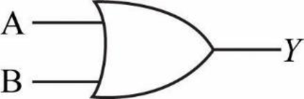
- The truth table for OR gate is as follows:
| INPUT A | INPUT B | OUTPUT Y |
| 0 | 0 | 0 |
| 0 | 1 | 1 |
| 1 | 0 | 1 |
| 1 | 1 | 1 |
NOT gate:
- The NOT gate refers to a logic gate whose output will be HIGH when it’s input is LOW and whose output will be LOW when it’s input is HIGH.
- The symbol to represent NOT gate is given below:
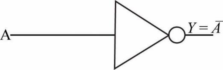
- The truth table for NOT gate is as follows:
| INPUT A | OUTPUT Y |
| 0 | 1 |
| 1 | 0 |
Explanation of Solution
b.
Logic gate circuit:
The logic gate circuit for the given relay ladder diagram is as follows.
Explanation:
In the above given logic gate circuit,
- The input “C” is connected to logic NOT gate and the corresponding output will be “
- Then the inputs “A”, “B”, “
- Now, the resultant along with the other input “D” is connected to a logic AND gate whose output will be
Expert Solution & Answer
Want to see the full answer?
Check out a sample textbook solution
Students have asked these similar questions
A3Q3.c - You are to write a C program that implements the following disk scheduling
algorithms:
a. FCFS [10 marks]
b. SCAN [10 marks]
c. C-SCAN [10 marks]
d. SSTF [10 marks]
e. LOOK [10 marks]
f. C-LOOK [10 marks]
•
Your program will service a disk with 300 cylinders numbered 0 to 299.
•
•
•
•
The program will service the requests (a list of 20 cylinder numbers) given in the file
request.bin.
This file contains (4 byte) integer values representing requests ranging from 0-299.
Your program will take the initial position of the disk head as the first command line
argument and the direction of the head as the second command line argument.
It will then output the requests in the order in which they are serviced, and the total
amount of head movements required by each algorithm.
In particular, your program needs to do the following:
Your program should take two command line arguments
a) First command line argument - initial position of the disk head (an integer value)
b) Second command line…
2. The memory management has contiguous memory allocation, dynamic partitions,
and paging. Compare the internal fragmentation and external fragmentation for
these three approaches. [2 marks]
3. Suppose we have Logical address space = 24 = 16 (m = 4), Page size=2² =4 (n = 2),
Physical address space = 26 = 64 (r = 6). Answer the following questions: [4 marks]
1) Total # of pages ?
2) Total # of frames ?
3) Number of bits to represent logical address?
4) Number of bits to represent offset ?
5) Number of bits to represent physical address?
6) Number of bits to represent a page number?
7) Number of bits to represent a frame number /
4. What is translation look-aside buffers (TLBS)? Why we need them to implement the
page table? [2 marks]
5. Why we need shared pages for multiple processes? Give one example to show the
benefits. [2 marks]
6. How to implement the virtual memory by using page out and page in? Explain with
an example. [2 marks]
7. We have a reference string of referenced page…
8. List three HDD scheduling algorithms. [2 marks]
9. True or False? The NVM has the same scheduling algorithms with HDD. Explain
why? [2 marks]
10. Why the modern mouses use polling to detect movements instead of interrupts? [2
marks]
11. What is thrashing? How does it happen? [2 marks]
12. Given a reference string of page numbers
7, 0, 1, 2, 0, 3, 0, 4, 2, 3, 0, 3, 0, 3, 2, 1, 2, 0, 1, 7, 0, 1
and 4 frames show how the page replacement algorithms work, and how many page
faults? [6 marks],
1) FIFO algorithm? [2 marks]
2) Optimal algorithm? [2 marks]
3) LRU algorithm? [2 marks]
13. List at least three file systems that you know. [2 marks]
14. In C programming, how the seek to a specific position in the file by offset? [2 marks]
Chapter 4 Solutions
PROGRAMMABLE LOGIC CONTROLLERS (LOOSE PA
Knowledge Booster


Learn more about
Need a deep-dive on the concept behind this application? Look no further. Learn more about this topic, computer-science and related others by exploring similar questions and additional content below.Similar questions
- Is developed App in play store much easier than in app store because i look app like human anonymus and like walter labs prioritize iphone app store first is it difficult to developed app on play store ? And btw i want to move to iphone anroid suckarrow_forwardQ12- A three phase transformer 3300/400 V,has D/Y connected and working on 50Hz. The line current on the primary side is 12A and secondary has a balanced load at 0.8 lagging p.f. Determine the i) Secondary phase voltage ii) Line current iii) Output power Ans. (230.95 V, 99.11 A, 54.94 kW)arrow_forwardmake corrections of this program based on the errors shown. this is CIS 227 .arrow_forward
- Create 6 users: Don, Liz, Shamir, Jose, Kate, and Sal. Create 2 groups: marketing and research. Add Shamir, Jose, and Kate to the marketing group. Add Don, Liz, and Sal to the research group. Create a shared directory for each group. Create two files to put into each directory: spreadsheetJanuary.txt meetingNotes.txt Assign access permissions to the directories: Groups should have Read+Write access Leave owner permissions as they are “Everyone else” should not have any access Submit for grade: Screenshot of /etc/passwd contents showing your new users Screenshot of /etc/group contents showing new groups with their members Screenshot of shared directories you created with files and permissionsarrow_forward⚫ your circuit diagrams for your basic bricks, such as AND, OR, XOR gates and 1 bit multiplexers, ⚫ your circuit diagrams for your extended full adder, designed in Section 1 and ⚫ your circuit diagrams for your 8-bit arithmetical-logical unit, designed in Section 2. 1 An Extended Full Adder In this Section, we are going to design an extended full adder circuit (EFA). That EFA takes 6 one bit inputs: aj, bj, Cin, Tin, t₁ and to. Depending on the four possible combinations of values on t₁ and to, the EFA produces 3 one bit outputs: sj, Cout and rout. The EFA can be specified in principle by a truth table with 26 = 64 entries and 3 outputs. However, as the EFA ignores certain inputs in certain cases, it is easier to work with the following overview specification, depending only on t₁ and to in the first place: t₁ to Description 00 Output Relationship Ignored Inputs Addition Mode 2 Coutsjaj + bj + Cin, Tout= 0 Tin 0 1 Shift Left Mode Sj = Cin, Cout=bj, rout = 0 rin, aj 10 1 1 Shift Right…arrow_forwardShow the correct stereochemistry when needed!! mechanism: mechanism: Show the correct stereochemistry when needed!! Br NaOPh diethyl ether substitutionarrow_forward
- In javaarrow_forwardKeanPerson #keanld:int #keanEmail:String #firstName:String #lastName: String KeanAlumni -yearOfGraduation: int - employmentStatus: String + KeanPerson() + KeanPerson(keanld: int, keanEmail: String, firstName: String, lastName: String) + getKeanld(): int + getKeanEmail(): String +getFirstName(): String + getLastName(): String + setFirstName(firstName: String): void + setLastName(lastName: String): void +toString(): String +getParkingRate(): double + KeanAlumni() + KeanAlumni(keanld: int, keanEmail: String, firstName: String, lastName: String, yearOfGraduation: int, employmentStatus: String) +getYearOfGraduation(): int + setYearOfGraduation(yearOfGraduation: int): void +toString(): String +getParkingRate(): double In this question, write Java code to Create and Test the superclass: Abstract KeanPerson and a subclass of the KeanPerson: KeanAlumni. Task 1: Implement Abstract Class KeanPerson using UML (10 points) • Four data fields • Two constructors (1 default and 1 constructor with all…arrow_forwardPlz correct answer by best experts...??arrow_forward
- Q3) using the following image matrix a- b- 12345 6 7 8 9 10 11 12 13 14 15 1617181920 21 22 23 24 25 Using direct chaotic one dimension method to convert the plain text to stego text (hello ahmed)? Using direct chaotic two-dimension method to convert the plain text to stego text?arrow_forward: The Multithreaded Cook In this lab, we'll practice multithreading. Using Semaphores for synchronization, implement a multithreaded cook that performs the following recipe, with each task being contained in a single Thread: 1. Task 1: Cut onions. a. Waits for none. b. Signals Task 4 2. Task 2: Mince meat. a. Waits for none b. Signals Task 4 3. Task 3: Slice aubergines. a. Waits for none b. Signals Task 6 4. Task 4: Make sauce. a. Waits for Task 1, and 2 b. Signals Task 6 5. Task 5: Finished Bechamel. a. Waits for none b. Signals Task 7 6. Task 6: Layout the layers. a. Waits for Task 3, and 4 b. Signals Task 7 7. Task 7: Put Bechamel and Cheese. a. Waits for Task 5, and 6 b. Signals Task 9 8. Task 8: Turn on oven. a. Waits for none b. Signals Task 9 9. Task 9: Cook. a. Waits for Task 7, and 8 b. Signals none At the start of each task (once all Semaphores have been acquired), print out a string of the task you are starting, sleep for 2-11 seconds, then print out a string saying that you…arrow_forwardProgramming Problems 9.28 Assume that a system has a 32-bit virtual address with a 4-KB page size. Write a C program that is passed a virtual address (in decimal) on the command line and have it output the page number and offset for the given address. As an example, your program would run as follows: ./addresses 19986 Your program would output: The address 19986 contains: page number = 4 offset = 3602 Writing this program will require using the appropriate data type to store 32 bits. We encourage you to use unsigned data types as well. Programming Projects Contiguous Memory Allocation In Section 9.2, we presented different algorithms for contiguous memory allo- cation. This project will involve managing a contiguous region of memory of size MAX where addresses may range from 0 ... MAX - 1. Your program must respond to four different requests: 1. Request for a contiguous block of memory 2. Release of a contiguous block of memory 3. Compact unused holes of memory into one single block 4.…arrow_forward
arrow_back_ios
SEE MORE QUESTIONS
arrow_forward_ios
Recommended textbooks for you
 Programming Logic & Design ComprehensiveComputer ScienceISBN:9781337669405Author:FARRELLPublisher:Cengage
 Systems ArchitectureComputer ScienceISBN:9781305080195Author:Stephen D. BurdPublisher:Cengage Learning
 Operations Research : Applications and AlgorithmsComputer ScienceISBN:9780534380588Author:Wayne L. WinstonPublisher:Brooks Cole
 C++ for Engineers and ScientistsComputer ScienceISBN:9781133187844Author:Bronson, Gary J.Publisher:Course Technology Ptr
 Principles of Information Systems (MindTap Course...Computer ScienceISBN:9781285867168Author:Ralph Stair, George ReynoldsPublisher:Cengage Learning
Programming Logic & Design Comprehensive
Computer Science
ISBN:9781337669405
Author:FARRELL
Publisher:Cengage
Systems Architecture
Computer Science
ISBN:9781305080195
Author:Stephen D. Burd
Publisher:Cengage Learning
Operations Research : Applications and Algorithms
Computer Science
ISBN:9780534380588
Author:Wayne L. Winston
Publisher:Brooks Cole
C++ for Engineers and Scientists
Computer Science
ISBN:9781133187844
Author:Bronson, Gary J.
Publisher:Course Technology Ptr
Principles of Information Systems (MindTap Course...
Computer Science
ISBN:9781285867168
Author:Ralph Stair, George Reynolds
Publisher:Cengage Learning